Home-->F1 Rocket Project

SITE CONTENTS 

     Background

     F1 Rocket Project

      Internet Resources

      Travel Stories

      Miscellaneous

Please send your comments and suggestions to:

Email Me

Copyright © 2008 by
Randy Pflanzer
Technology Professionals Consortium
All rights reserved


Links on this page:
    What is a F1 Rocket?
   
Where to put the Training Wheel?
   
The great "primer" debate.

Welcome to the main project page.  From here you can navigate to any aspect of the F1 Rocket construction effort that you'd like to see.  Below, in the status section, you'll find all of my assembly pictures and narrative for every phase of my project.  You can start at the beginning and page sequentially through every page or you can click on just a specific item of interest.


  Setting Up Shop   Fuselage (continued)   ENGINE (continued)
       Shop Space        Rudder Pedals                                    Engine Controls                       
       Shop Tools                                        Instrument Panel                                Crankcase Heater                    
       The Hangar                                     Canopy Rail                                       EGT/CHT Probes                     
         Pilot's Seat Back                                 Mount the Propeller                 
  Kit Arrival        Boot Cowl/Cowl Flange              
         Passenger Seat Panels                  Rig/Final Assembly
  Vertical Stabilizer        Rear Headphone Wiring                     Horizontal Stabilizer                       
       Assemble Rear Spar        Tail wheel                                          Vertical Stabilizer                           
       Assemble Front Spar        Electric Seat Heaters                             Elevators                                      
       Attach Ribs          Rudder                                        
       Rivet Skeleton   Wings        Empennage Wiring                     
       Jig Skeleton        Wing Prep        Rear Access Panel                         
       Skin and Skeleton Prep        Attach Aileron        Empennage Fairing                     
       Rivet Skin        Flap Brace        Throttle Quadrant                       
       Tip Fairing                                         Electrical Conduit        Switch Quadrant                        
         Rivet Inboard Ribs        Forward Floor Panels                 
  Rudder        Prep Bottom Skin        Control Stick                            
       Attach Stiffeners        Rivet Bottom Skin        Fuel Valve                                 
       Assemble Skeleton        Attach Flaps        Center Console                          
       Jig Skins        Attach Tie Down Ring        Throttle Cable Bracket                
       Rivet Rudder        Attach Wing Tip        Center Tunnel Support Angles    
       Roll Leading Edge        Wing Tip Electrical Stuff        Cockpit Lighting                         
       Attach Counterweight        Install Wing Tip Lens        Finish Interior                            
       Bottom Fairing                                   Final Wing Tip Attachments                Restraint System                        
       Top Fairing                                      NACA Inlet                                        Carpeting                                  
         Heated Pitot Tube                              Comm Antenna                         
  Horizontal Stabilizer          Instrument Sub-Panels              
       Assemble Rear Spar   Canopy        Firewall Protection                     
       Assemble Front Spar        Windshield Bow                                     Instrument Panel                      
       Assemble Skeleton        Canopy Tracks                                  Map Box                                   
       Drill Skins        Windshield Skins                                Interior Panels                          
       Rivet Skins        Canopy Frame                                   Behind the Panel                      
       Tip Fairing                                      Fit Frame to Fuselage                         Music in the Cockpit                 
         Canopy Removal Trick                      Fresh Air Vent                          

  Elevators

       Fitting the Plexiglass                          Fitting the Wings                      
       Attach Stiffeners        Side Skirts                                         Rigging the Flaps                     
       Assemble Skeletons        Rear Skirts                                         Rigging the Ailerons                 
       Attach Right Elevator Skin        Rear Canopy Lock                             Mounting the Magnetometer    
       Left Elevator Trim Motor Mount        Final Assembly                                   Upper Gear Leg Fairing            
       Attach Left Elevator Skins        Canopy Stops         Wing Root Fairing                   
       Elevator Trim Hinge Pin        Windshield                                         Fuel Pump Assembly               
       Rivet Left Elevator        Final Finish                                  
       Assemble Trim Tab     FIRST FLIGHT PREP
       Wire Trim Tab Motor   ENGINE        Register with FAA                      
       Attach Counterweight        New Mount                                           Initial Engine Start                   
       Tip Fairing                                       Mount the Mount                                  Weight and Balance                
         Gear Legs/Wheels/Tires                        Pilot's Operating Handbook     
  Fuselage        Wheel Pants                                          FAA Inspection                       
       Empennage Deck        Gear Leg Stiffeners                           
       Rudder Cable Slots        Gear Leg Fairings                            FLIGHT TESTING   
       Rear Baggage Floor        Brakes                                                First Flight                               
       Battery Cover                      Pick-up Engine                                Flight Testing                         
       Elevator Autopilot Servo        Firewall Prep                                    Injector Balancing                  
       Battery Tray                                       Mount Engine                            
       Rudder Cables                                     Alternators                                  Wiring Diagrams
       Static Air Ports                                    Prop Governor                                Introduction                             
       ELT Tray                                            Exhaust                                           Overview                                  
       Battery Solenoid                                 Heat Muffs                                       Individual Drawings                  
       Wiring Runs                                       Engine Wiring                           
       Forward Baggage Panels                    Engine Cowl                              Instrument Panel             
       Passenger Floor Panels                       Oil Dipstick Door                             Proposed F1 Panel                      
       Passenger Crotch Strap              Cowl Scoop                                    Final Product                              
       Mk. 2 Flap Installation                         Air Box                                     
       Passenger Seat Back                           Engine Baffles                             Paint Scheme
       Control Tubes                     Plenum                                      
       Aileron Autopilot Servo                      Oil Cooler                                  
       Electric Aileron Trim                           Purge Valve Connections           
       Front Seat Floor Panel                       Ignition Wiring                          
       Front Seat Crotch Strap                     Cooling Tubes                           
       Longeron/Firewall Reinforcement        Crankcase Vent                          


What is a F1 Rocket?

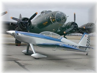
The F1 Rocket is an awesome, affordable, high-performance, kit-built airplane.  It is an all-metal airframe crafted and designed for the discriminating pilot that seeks F-16 like performance at an affordable price. It is capable of climbing at 3,500 fpm and leveling off at 10,000 feet five minutes later for a 230+ m.p.h. cruise.


Tom Martin's beautiful HRII Rocket

The airframe comes as a quick build kit, which means that a majority of the construction is already assembled for you.  
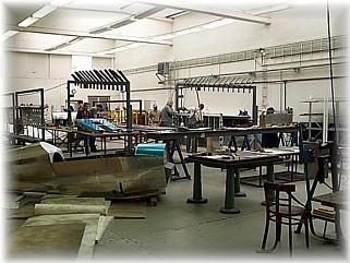
The airframes are meticulously built by highly trained professionals from HPA International, a manufacturing subdivision in the Czech Republic.

All wing ribs and internal wing parts are anodized for the highest corrosion protection available.  All wing skins are primed with epoxy chromate.  The F1 Rocket wings are delivered with the spars completed, all ribs riveted in place and the top skins riveted on. The builder will need to install the wiring necessary for landing lights, strobe and position lights, and pitot tube hardware.  Once this has been completed, the bottom skins can be riveted in place.


A look inside the HPAI shops in the Czech Republic

The fuselage is delivered with all bulkheads completed and all skins riveted in place.  All bulkheads and internal parts are anodized for corrosion protection.  All skins have been primed with epoxy chromate for corrosion resistance.  The ELT and battery trays are preformed and ready for final assembly and installation.  All fuselage floor and baggage compartment panels are pre-cut and pre-drilled ready to install.  The builder will install the torque tube and control sticks, rudder pedals and cables, seats and seatback support, and instrument panel.

The finish kit is the most complete and comprehensive finish kit that can be provided.  Most parts that are considered upgrades by other manufacturers, are standard in this kit.  Fiberglass wing root fairings, fiberglass gear leg and gear leg intersection fairings, Rocket-tip wingtips with strobe and position light bulkheads pre-molded into place with Lexan Plexiglas covers are all included as standard.  The cowl is delivered in three pieces for ease of installation.  The oil door is pre-molded for ease of construction.  The canopy is a slider canopy.  The gear legs are manufactured from titanium and are pre-drilled to the engine mount.  The wheels, brakes, tires, tubes, brake lines, pitot lines, master cylinders, and fuel lines are all included in the finish kit.

The empennage kit is not included in the Quick Build Kit and is considered a starter kit.  This is done for two reasons:  1) This gives first time builders an opportunity to discover mistakes on parts that are not expensive rather than on areas that are very expensive.  2) When Team Rocket went through the FAA 51% certification process, it was determined that they could do considerably more of the difficult construction on the wings and fuselage by making the tail its own kit.


The F1 Rocket Empennage kit

The F1 Rocket is powered by a fuel-injected Lycoming IO-540 engine.  Horsepower ranges from 250 to 300+ and either a 2- or 3-bladed prop can be used. The engine is not included in the kit

If you want the full scoop on the F1 Rocket, visit the Team Rocket web site by clicking here.


Where to put the Training Wheel?

Pilots like to debate.  No, forget that.  Pilots like to argue……sometimes vehemently over some insane topic.  None stokes the fire like a good tail wheel/nose wheel debate.  Or like us tail wheel pilots like to say, "Where are you going to put the training wheel, up front or in back?"

The reason this issue even comes up at all is that when a builder makes the choice of which airplane to build, they often have the option to build either a tail dragger or nose dragger.  For the Rocket crowd, there is only one option at the moment.  But for the RV crowd, each model can be built in either configuration.

Having built and flown a RV-6, and being a relatively low time pilot (less than 600 hours), I feel at least as qualified as other pilots to have an opinion.  If you are stuck in this quandary and can't decide which model to build, my advice is to build the configuration you are most happy with and most comfortable flying.

There is no right or wrong choice.  I built a tail dragger because I liked the way it looked and I wanted the challenge of learning to fly one.  I found the RV-6 to be a piece of cake to land.  You have to stay on the rudders all the way to the hanger but I didn't find it difficult to master.  During my tail wheel endorsement instruction, I found the Citabria much more difficult to handle, especially in a crosswind.  I became so comfortable landing the RV-6 that I routinely flew in 20-25 knot crosswinds without worry.  I even landed it once in a 40-knot crosswind in Arizona. 

It is my opinion that the nose dragger versions are safer and less likely to experience a landing accident.  I say this because the physics say so.  Nose draggers are inherently safer because the center of gravity is forward of the main gear.  In a tail dragger, it is reversed and in the wrong hands, a tail dragger will swap ends on you.  That doesn't make it more dangerous, just more prone. 

I think Van's sells about equal number of tail draggers and nose draggers.  In the group I fly with, tail draggers are the predominant configuration.  Everyone's situation is different.  Don't let your ego or the ribbing of your fellow aviators sway you one way or the other.  Pick what's right for you and don't look back. 

I recently saw this on the Matronics email list and thought it was appropriate.  I didn't write it and would gladly give the author due credit if I knew who he/she is.  If you do, drop me a line and let me know.

Ode To The Tail dragger

Tail dragger, I hate your guts.
I have the license, ratings and such,
But to make you go straight is driving me nuts.
With hours of teaching and controls in my clutch
It takes a little rudder....easy, that's too much !

You see, I learned to fly in a tricycle gear
With one up front and two in the rear.
She was sleek and clean and easy to steer,
But this miserable thing with tires and struts
Takes a little rudder.....easy, that's too much !

It demands your attention on the takeoff roll,
Or it heads towards for the boonies as you pour on the coal.
Gotta hang loose, don't over control.

This wicked little plane is just too much
With a lot of zigzagging and words obscene
I think I've mastered this slippery machine.
It's not too bad if you have the touch
Just a little rudder....easy, that's too much !

I relax for a second and from the corner of my eye
I suddenly realize, with a gasp and a cry
That's my own tail that 's going by!
You ground looping wreck, I hate your guts,
Give a little rudder....Good Lord, THAT'S TOO MUCH !
 

The Great Primer Debate

This 
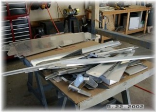
is major argument number two among builders.  The question is whether to prime perfectly good Alclad aluminum or not.  There is no debate about whether to prime non-clad parts.  You must prime these parts because they will corrode and relatively quickly.  These parts are usually easy to prime and represent a small percentage of the airframe.  They are usually small parts like hinge, plate, angle, bar, and anything steel like engine mounts, gear legs, etc.


All the priming equipment you'll ever need

No, the real primer war issue centers on priming parts that are fabricated out of Alclad aluminum sheet.  These parts tend to represent the major structural components like ribs, bulkheads, and skins.  And the answer to the question is "It depends."

It depends upon your circumstances.  If you live in a salt air environment and your airplane will see a lot of time outdoors, then I think you have a glimmer of an argument for priming.  The problem is that the way most folks prime, they are not improving the corrosion protection over the Alclad.  I'll speak more about this in a second.  If you don't live on the coast, then I think additional priming is 
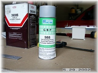
a waste of time, money, and weight.

To do priming right, you need to prep the surface so that the primer will adhere properly.  This usually means acid etching the surface.  Then, you need to apply a primer that is an effective water barrier.  The most common primer is a metal-etching wash primer.  This type of primer is NOT an effective water protection barrier and the instructions usually state that it must be top coated in order to maximize the protection.  Epoxy two-part primers are the most effective since they are water barriers but they are the most toxic and the most time consuming to apply.  Starting to get the picture?  To prime and to do it properly takes a lot of time, careful procedures, and expensive and toxic primer.

The benefits of going to all that work to prime an airplane that will be hangared and babied its whole life are marginal at best.  Have you ever peered inside the fuselage or wing of a 40 year old Cessna?  Know what you'll find?  Bare Alclad aluminum that's what and very little, if any, corrosion. 

My strategy for priming is to only prime the parts that need it.  If I get any indication of corrosion, Cessna makes a corrosion stopping/prevention fogging agent.  If I'm so inclined, I may fog the inside of my bird once it's painted. 


"Fate is for those too weak to determine their own destiny." 

- Kamran Hamid