|
|
| Home-->F1 Rocket Project-->Vertical Stabilizer Page 2 |
|
SITE CONTENTS
Please send your comments and suggestions to: Copyright
© 2002-2005 by |
Links
on this page: Skin and Skeleton Prep Rivet Skin Tip Fairing |
|
|
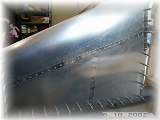
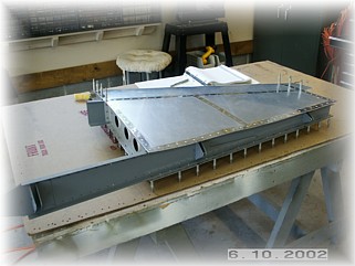
Skin and Skeleton Prep
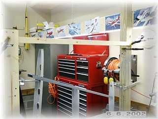
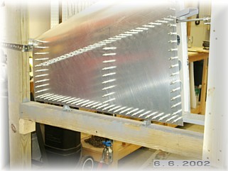
I've attached a "story board" across the top of the jig. This is nothing more than a board on which I can transfer measurements and the extended centerlines of the ribs. I've also carefully marked a centerline on each rib and spar in red permanent marker. When I'm drilling holes, I will lightly drill through the skin without drilling into the spar/rib. That way I can peak inside the hole to make sure that I'm aligned with the centerline of the spar/rib.
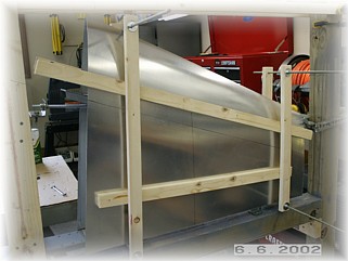
Before drilling any holes, it is important to ensure that the skin is pressed tight against the skeleton. If the skin is not tight, then the rivets will cause dents in the skin when they are set. I made a couple to clamps out of 1" X 3" boards and threaded rod. It takes a little jiggling to get this fixture set. Once on, I verified that the skin extended past the bottom spar and the top and bottom ribs at least the minimum distance. Then, I transferred my measurements for the forward spar and the middle rib to the skin. I started drilling the skin at the intersection of these two parts and then worked my way outward and down. I also put a cleco in every single hole as I went to get the skin tight. I did this to both sides of the vertical stabilizer.
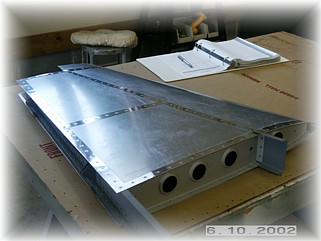
Once the center holes are drilled and fastened with clecos, I removed the clamps and boards. I marked the remaining centerlines on the skin and continued drilling and clecoing the skin until both sides we finished. At this point the skin was removed and both the skin and the skeleton prepared for final assembly and riveting.
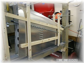
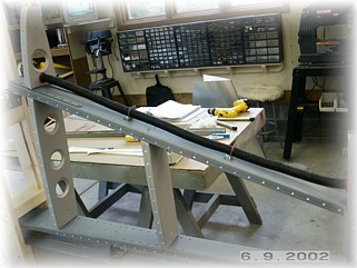
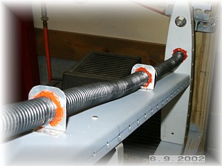
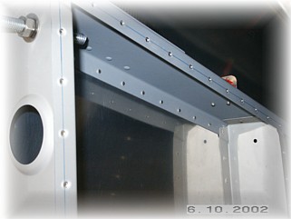
I decided to add some electrical conduit to the front spare in case I later decide to put something in the tip of the vertical stabilizer. At this point I'm not planning on anything up there, but you never know. Possibilities include a glide slope/VOR antenna or a small camera. I used some lightweight plastic conduit that Van's sells and made a couple of clips from scrap. They are pop riveted on and the tubing secured with RTV. The rivet holes in the skeleton were prepped and dimpled. The skin was trimmed to the proper overhand on just the rear spar and bottom rib. I left the skin longer than necessary along the top rib so that it could be trimmed in conjunction with the rudder later on. The plastic coating on the inside of the skin was removed and the outer plastic removed just along the rivet lines using a hot solder gun and a smooth tip.
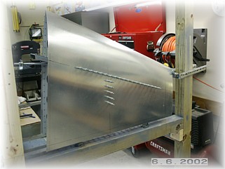
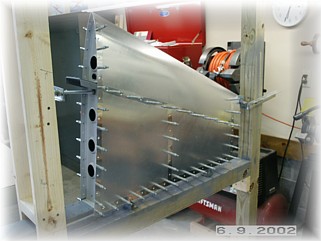
After dimpling the skin, I attached it to check the fit. Everything looks good and I'm ready for the next step.
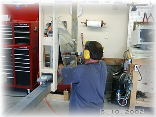
Riveting the skin on the vertical stabilizer is relatively easy. I first rivet on one side with the other side open for access with the bucking bar. The only rivets that need to be set are on the front spar and the middle rib. Start at the intersection of the middle rib and front spar and work your way out and down. Be sure to cleco the skin along the rear spar to prevent any skin creepage.
BEFORE setting any rivets on the other side, be sure to first remove the nuts and washers from the threaded rod inside the skeleton. I almost forgot to do this. If you do forget, you may still be able to free up the stabilizer from the jig but remembering beforehand will certainly make it easier. Riveting this side is a little more tricky than the other. You can reach inside the skeleton by gently pulling the skin back but be careful to not pull it back too far or you may stretch the skin slightly. With a little care, you can reach all the rivets. Again, start at the intersection of the middle rib and the front spar and work your way down and out evenly. The last few rivets in the bottom of the middle rib were the toughest because my fat arm tends to not let the skin lie flat against the rib. I carefully pressed the skin flat with the gun before hitting the trigger.
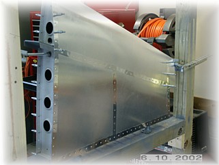
With the center rib and front spar rivets done on both side, the stabilizer can be removed from the jig and placed on the work bench. I set almost all of the remaining rivets with the squeezer. I couldn't reach the last four rivets on the top rib tip with the squeezer but I could get a bucking bar in there. There are two "gotchas" that can reach up and grab you at this point. One is that you may not be able to get a squeezer on some of the rivets along the rear spar if the holes are too close to the edge of the reinforcing plate that is on the aft face of the spar. I learned from building four other empennages so I put my holes along the rear spar flange slightly off center by cheating a little towards the edge. Fortunately I could get a bucking bar on all my rivets. The other "gotcha" is that you may have difficulty reaching a rivet or two if they happen to line up too close to one of the hinge brackets. I almost got them all in but I had trouble with one rivet. Rather than spend too much time worrying about it, I just put in a pop rivet. I'll fill the hole later and when it's painted, no one will be able to tell that it's a pop rivet.
With that, the vertical stabilizer is as completed as it can be until the rudder is finished and the rest of the airframe kit arrives from Texas in August.
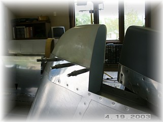
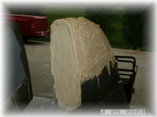
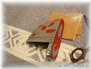
To install the tip, I first drilled the fairing to the skin, making sure that I had the proper profile with the rudder. I also made a blue foam rib to insert into the fairing so it will hold its shape. I covered the rib with two layers of fiberglass cloth and let it set up overnight. After protecting the skin with some duct tape, I screwed the fairing into place and prepared it for filler.
I slathered on some dry micro-balloon mix and let that set up overnight as well. After sanding it smooth enough to remove the screws, I took it over to my workbench and began filling the pin holes with spot putty. It usually takes me about three rounds of this to get them all covered, sanded, and primed.
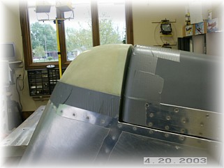
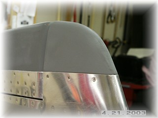
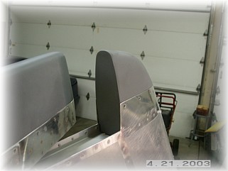
This is what the tip looks like mounted. That fully completed the vertical stabilizer. It is now ready for primer and paint. |
||
|
"Man's
maturity: to have regained the seriousness that he had as a child at
play." |