|
|
| Home-->F1 Rocket Project-->Engine Page 3 |
|
SITE CONTENTS
Please send your comments and suggestions to: Copyright
© 2008 by
|
Links
on this page: Gear Leg Stiffeners Gear Leg Fairings |
|
|
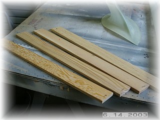
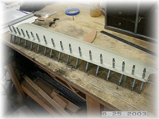
Contrary to the plans, I intend to go ahead and add the gear leg stiffeners now, rather than wait to see if I have any gear leg shuffle. I'd rather so all this work now while I have the airplane in my shop rather than later at the airport. I went to Home Depot and picked up four pieces of fir. Since I couldn't find the wood in the appropriate thickness, I decided to just glue two pieces together to make up a single stiffener.
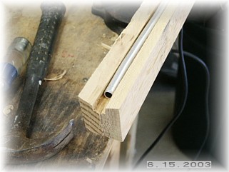
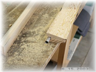
After the glue dried, I made some initial cuts on my table saw. First, I cut the edge at an angle to allow the gear leg to settle into the stiffeners. I then cut a groove out down the inside center for a piece of 3/8" aluminum tube. I plan to run my brake line down the inside of this tube. I then beveled the stiffeners down their entire length so that the rear edge was about 1/2" thick.
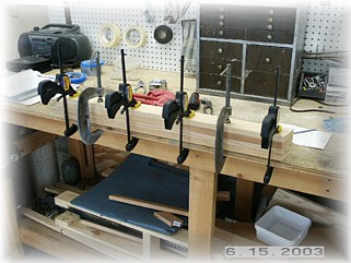
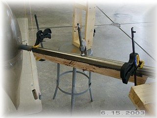
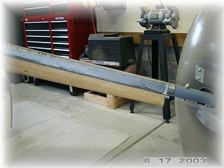
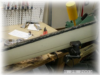
After mixing up a healthy dose of proseal, I mounted the stiffeners to the leg and clamped them in the proper position. I used two plumb bobs to ensure that the stiffeners where in trail. After setting up overnight, I used a sander to smooth out the stiffeners and to round off the edges. I then glassed the stiffeners to the leg with two layers of fiberglass cloth.
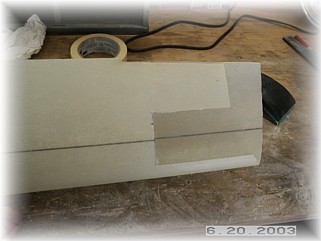
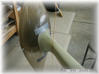
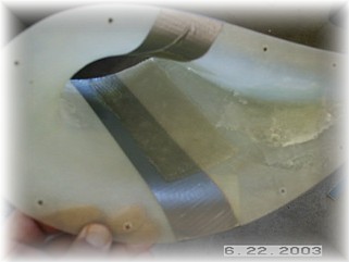
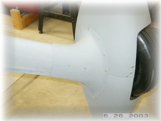
I made some initial cuts on the gear leg fairing so that it would lay flay against the upper surface of the gear leg. I marked the 30% chord line on the fairing too. These lines will be used to center the fairing on the gear leg. I also trimmed the lower intersection fairing so that it had about a 1" flat surface all around the edge.
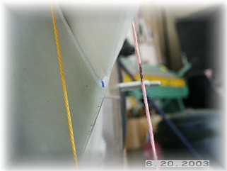
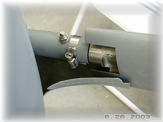
I had to remove the lower gear leg socket so that I could slip the lower intersection fairing onto the gear leg. I then bolted it back on, installed the gear leg fairing, and dropped two plumb bobs. I moved the intersection fairing around until I had the gear leg fairing resting against the upper surface of the gear leg, centered on the chord line, and in trail. I marked the center of the rear edge and centered between the two plumb bobs. When I had it in place, I marked its location and then taped it in position and double checked the measurements.
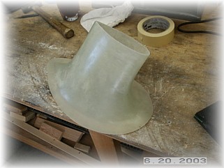
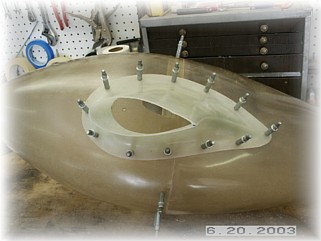
Over on the bench, I measured for and drilled mounting holes. I thought a bit about how to mount the lower intersection fairing. I couldn't mount it permanently to the wheel pants because I can't get to the upper mounting screws if I do. So the intersection fairing must be removable. I then looked at leaving it in one piece, but just couldn't find a way to get to the lower edge of the gear leg fairing to pull the hinge, so I decided that the intersection fairing would be split in two.
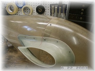
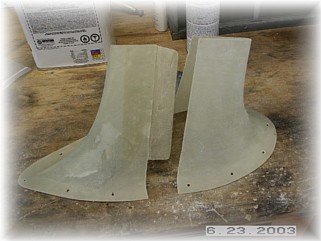
I decided to split the fairing in the middle, in line with the split in the wheel pants. I drew a line on the fairing and then put a piece of duct tape along the line on the inside. I then laid up a three ply fiberglass flange on both the upper and lower surface of the fairing on the inside. Once it set up, I carefully cut the part in two with my Dremel cut off wheel.
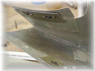
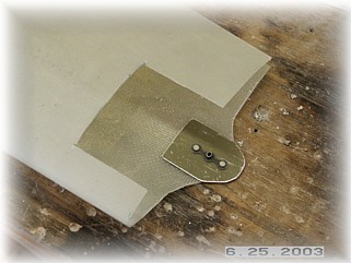
When attaching the two halves, I decided to have the upper screw on the bottom side hold the gear leg fairing in place too. This will prevent the gear leg fairing from walking up or down the gear leg while still allowing it to flex. I added a tab at the bottom of the gear leg fairing and cut the remaining lower section off.
The final piece of the puzzle is to attach the hinge to the trailing edge of the gear leg fairing. I placed the hinge inside the fairing so that the trailing edges close around the hinge. When finished, you'll never know the hinge is there. I carefully clamped and drilled the holes into the hinge, making sure that the trailing edge was straight. I then got out some "Black Death", better known as Proseal, and riveted the hinge to the fairing.
I left the hinge pin long and trimmed it so it bent up to and across the gear leg. I then secured it with a worm clamp. All that is left to do is to run the brake line down through the support tube in the back of the gear leg and around the axle to the brake cylinder. That's on the next page. |
||
|
"Things should be made as simple as possible, but no simpler." |