|
|
| Home-->F1 Rocket Project-->Fuselage Page 3 |
|
SITE CONTENTS
Please send your comments and suggestions to: Copyright
© 2008 by
|
Links
on this page: ELT Tray Battery Solenoid Wiring Runs Forward Baggage Panels |
|
|
ELT Tray
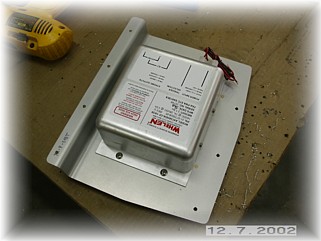
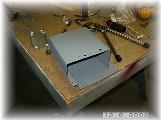
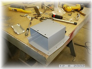
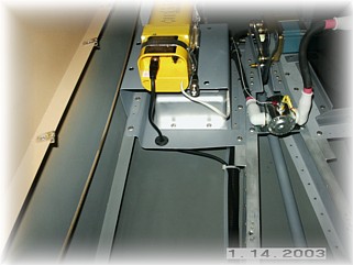
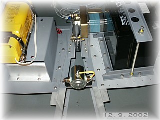
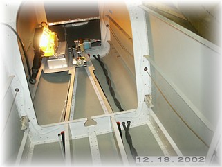
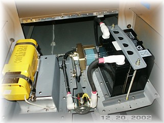
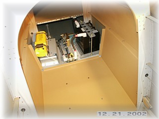
I intend to use the ELT tray to hold both the ELT and the strobe power supply. Since the strobe power supply weighs more than the ELT, I mounted it on the bottom and made a tray bracket and riveted it to the ELT tray. I added access holes so that I could get to the screws of the power supply and all the appropriate nut plates.
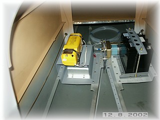
When it was all assembled, I installed it in the fuselage. I will do some final routing of all the wires later, once I add the battery cables and starter solenoid. From the picture, you can also see that I've finish painted the inside of the baggage area as well.
After thinking about it for awhile, I decided to mount my ELT antenna on top of the rear seat right armrest. I used grommets in the panels to route the antenna wire forward and up the forward edge of the rear seat bulkhead.
Here, the antenna is mounted. At the top, I held the antenna with a couple of plastic clamps to keep it from banging up against the bulkhead. I MAY have a little interference problem with the sliding canopy, but I don't think so. I'll have to wait until I get to the canopy to find out. I'm pretty sure the canopy frame is far enough off of the bulkhead to miss the antenna.
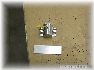
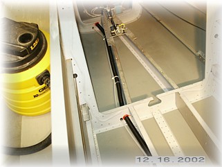
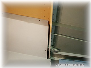
I installed the battery solenoid per the plans using the material provided in the kit. As I installed this, I began to visualize where all the wires are going to go. Since the positive terminal of my battery is on the forward end, I will run the wire down and across the front of the battery right to the post on the solenoid and using a cushion clamp to hold it. The output side will run to the rear, along the ELT tray and duck under the fuselage bulkhead and into a tube for all the wires. This will keep the wires out of the way and make for a neat installation.
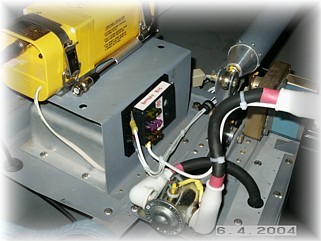
Above is an updated picture of this area which shows the addition of a battery bus. This provides an alternate feed to my avionics in the case of a battery contactor failure. See the wiring diagrams for the details.
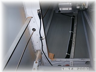
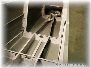
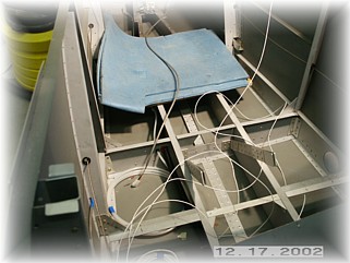
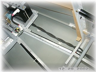
Before installing the remaining baggage panels, I decided to go ahead and finish up the wiring runs from the rear of the fuselage going forward. This became a whole lot bigger job than I thought, but I wanted to get it done now instead of pulling all the panels, battery tray, and ELT tray out later. I installed some plastic conduit on both side of the fuselage because all the wires I had wouldn't fit into just one. On the right hand side, I ran the static air line next to the wire run and tied it off to the conduit.
It is amazing just how quickly the wire bundles start to add up and make a mess. Included in my run was the bundle to the autopilot servo. That alone required nine wires!
Lastly, I ran both positive and negative battery cables forward. I used some welding cable that I bought locally. This stuff is super tough and very flexible. If you are wondering why I am running a negative cable from the battery instead of just grounding it locally, read Bob Nucholls book on aircraft wiring at www.aeroelectric.com. With the runs complete, I finished up the end wiring by attaching the wires to the battery, solenoid, autopilot servo, ELT, and strobe power unit. I also had the wires from the elevator trim motor and rear position light to run forward.
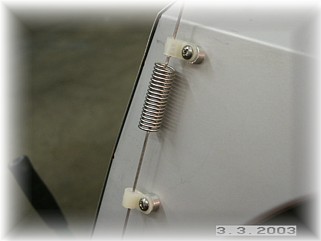
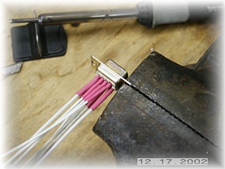
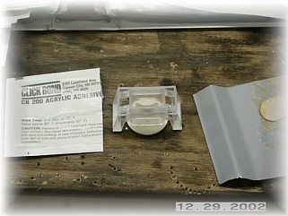
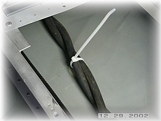
To hold down the battery cables between ribs, I installed some Click Bond cable ties. You basically mix up some epoxy that smells like something from your dentist's office, and use the plastic fixture to hold the cable tie in place on your structure until the epoxy sets.
This is what the cable tie looks like after the plastic installation guide is removed. All that's left is to slip a tie wrap through the fitting and around your cable and you're all done.
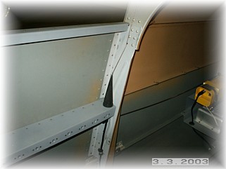
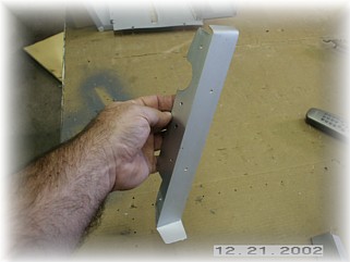
I've found that on most Rocket kits, the forward baggage panel comes up a little short where the sides rest against the rear seat bulkhead. I don't like the looks of that so I built a couple of FUBAR angles out of some soft aluminum stock that I bought at my local hardware store. What is FUBAR you ask? Go rent the movie "Private Ryan" or ask any military buddy of yours.
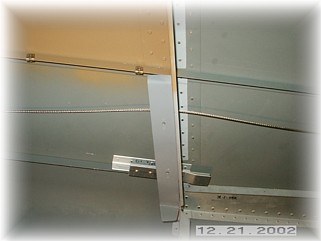
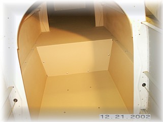
I pop riveted the FUBAR angles onto the rear edge of the rear seat bulkhead and placed a couple of nut plates along the side to attach the forward baggage panel to it. Here it is all painted with the panel attached.
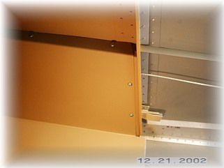
I went ahead and painted and attached the final two baggage panels. That pretty much completes everything rear of the back seat. The only things I will need to do is attach the elevator push rods once the control system is installed and install the ELT antenna, which will go on the rear empennage deck. Next, I will focus on the remaining interior floor panels. |
||
|
"Always do right; this will gratify some and astonish the rest." |