|
|
| Home-->F1 Rocket Project-->Rig/Final Assembly Page 9 |
|
SITE CONTENTS
Please send your comments and suggestions to:
Copyright © 2002-2005 by |
Links
on this page: Fresh Air Vent Fitting the Wings Rigging the Flaps Rigging the Ailerons |
|
|
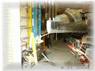
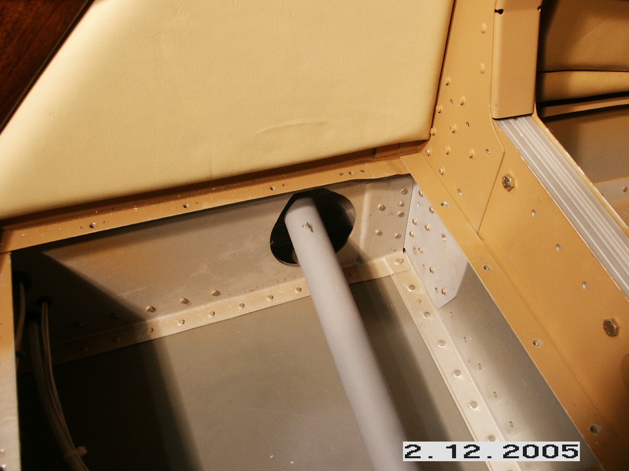
I plan to pull my fresh air from a NACA vent on the side of the fuselage. To get started, I leveled the fuselage. I then made an outline of the NACA vent and leveled it longitudinally. The location of the opening is strictly based on convenience. I have more room on the right side and I placed it just above my interior leather panel.
Before using some proseal to glue the vent to the inside of the fuselage, I cut some screen to fit across the opening. I glued this to the NACA vent before mounting the vent to the fuselage. That way, it stayed in place. I applied the proseal around the edges and across the screen and mounted it. After waiting overnight, I used some bondo to smooth the edges and create a smooth transition to the vent. After a little primer, it was all done.
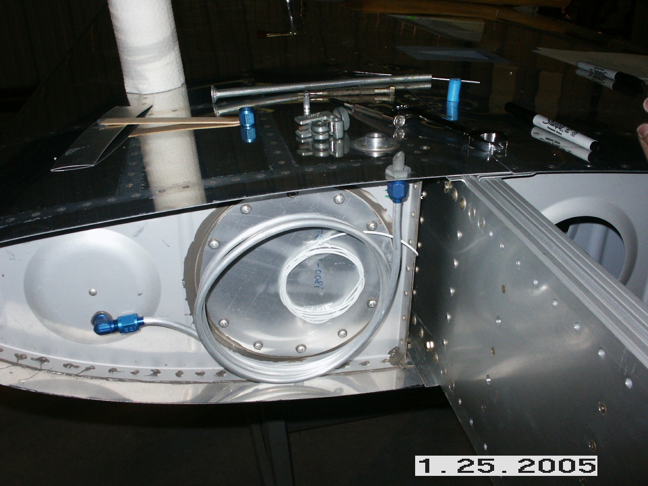
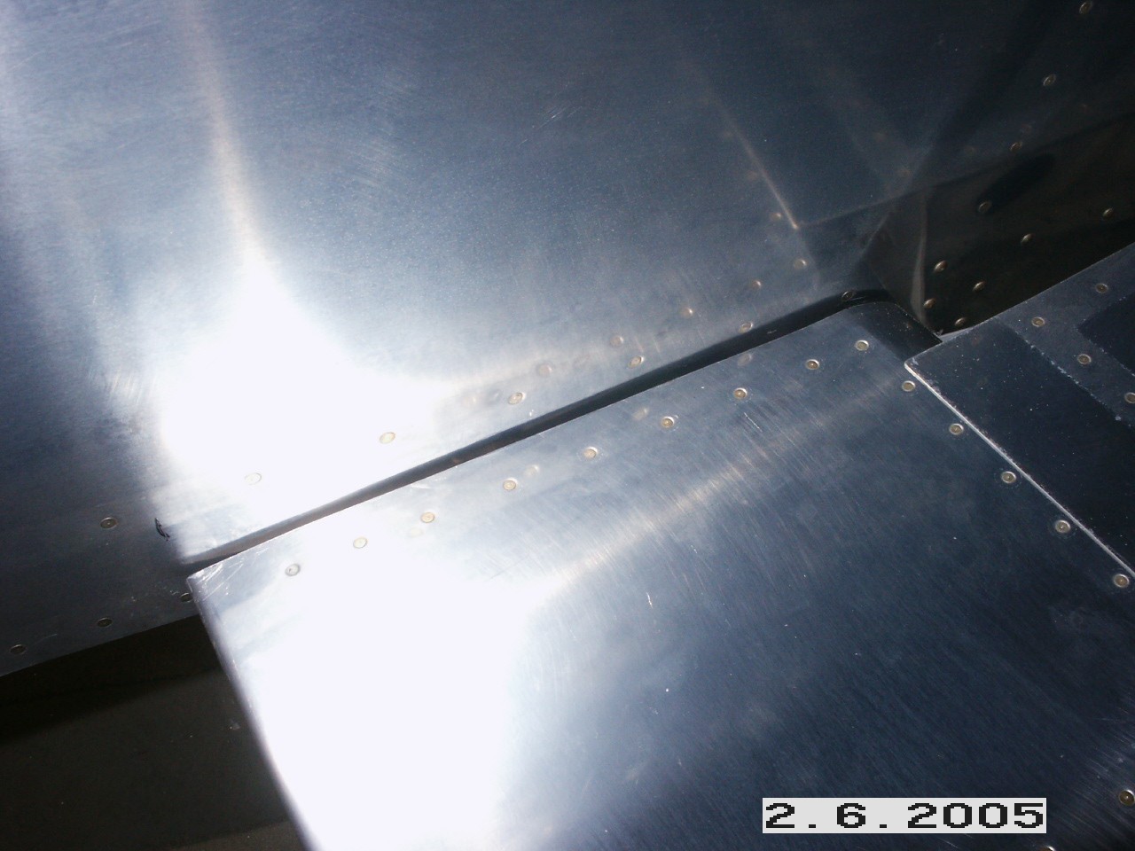
Prior to fitting the wings into the fuselage for the first time, I went ahead and installed the fuel tank vent. I used a double loop of tubing and fit it to a union fitting that I glued into a hole. I trimmed the end of the fitting off at a 45 degree angle and rounded the edges smooth. I then inserted the wings into the fuselage and temporarily bolted them in with about 4 bolts each. They went in without trouble and fit perfectly. Be sure to watch that bottom skin when you slid the wing in. It wants to catch on the inside rib and you need to coax it over the outside of the bottom skin.
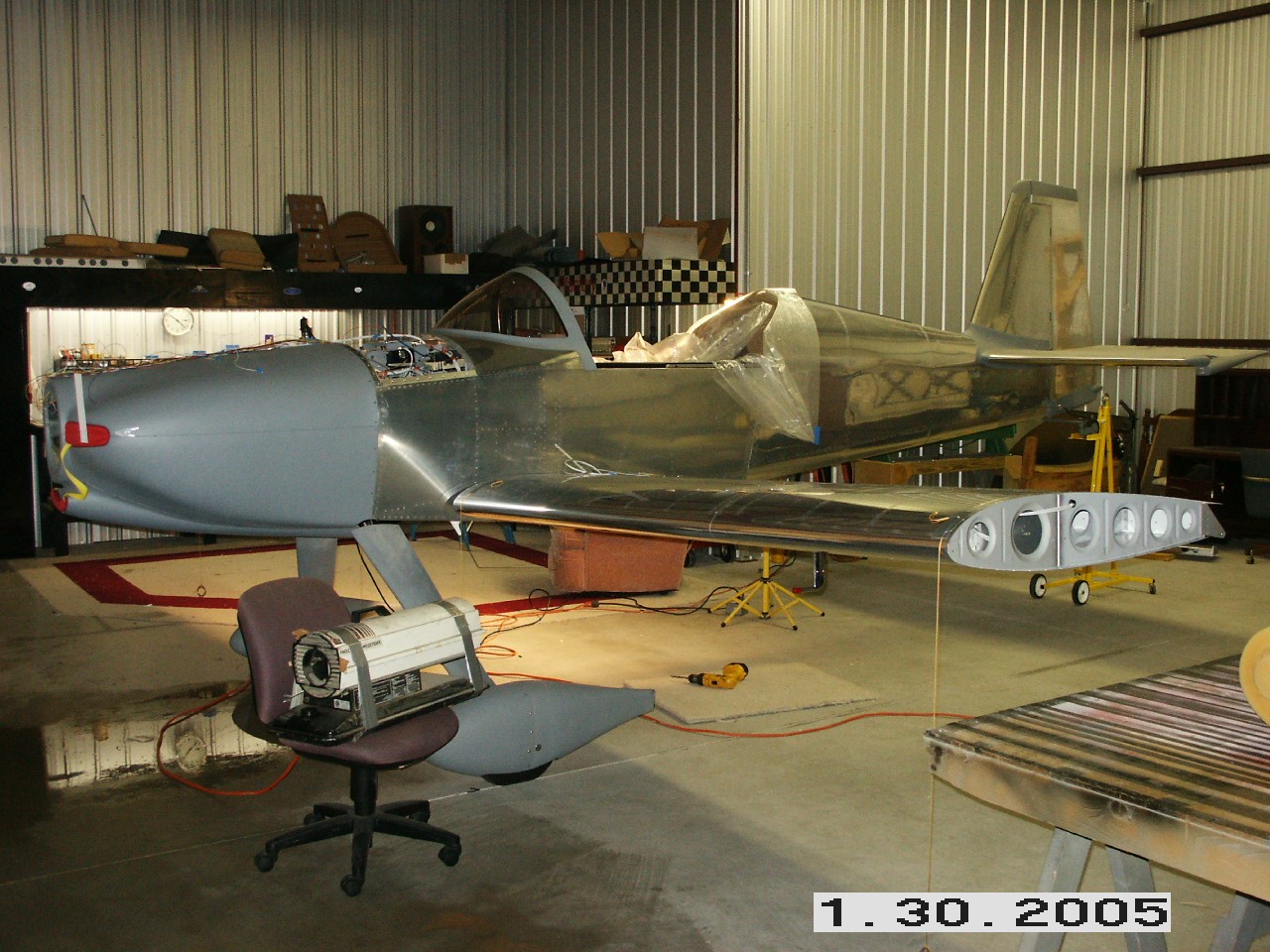
Next I set the incidence according to the plans and marked the top of the rear spar. Then, I dropped four plumb lines off of the wings and aligned them all in a row. To double check, I measured from the wing tips back to the tail wheel and also to the horizontal stabilizer. Both sides measured the same so I marked the rear spar again along the outside edge. I used the measurements in the instructions to find the center hole in the rear spar and made a mark on the fuselage spar for the pilot hole. After successively drilling the holes up to 5/16", I stuck a bolt in and tightened it down. I went back and rechecked the incidence and sweep to make sure they hadn't changed. It's a good thing they remained the same because I'm not sure what you would do if they had changed. When this is assembled for the final time, I plan to use a lock nut rather than a castellated nut and cotter pin.
After removing the wings to finish up the plate nuts in the root rib and the tank attach bracket, I reinserted the wings into the fuselage and bolted them up. It was a tougher job than I thought because my wiring looms interfered with the bottom bolts. It took awhile, but I finally was able to get a wrench on them. The right picture shows you my tank bracket. DO NOT follow the outline in the plans. I did and it was way off. My bracket has a horizontal slot cut into it to allow the attach bolt to slide out of the bracket if I have an off field landing and the wing breaks back. That way, the wing will separate from the bracket without pulling the end of the fuel tank off thus avoiding a major fuel spill. I used two wide area washers and just tightened the bolt down snug, but not too tight.
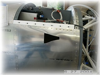
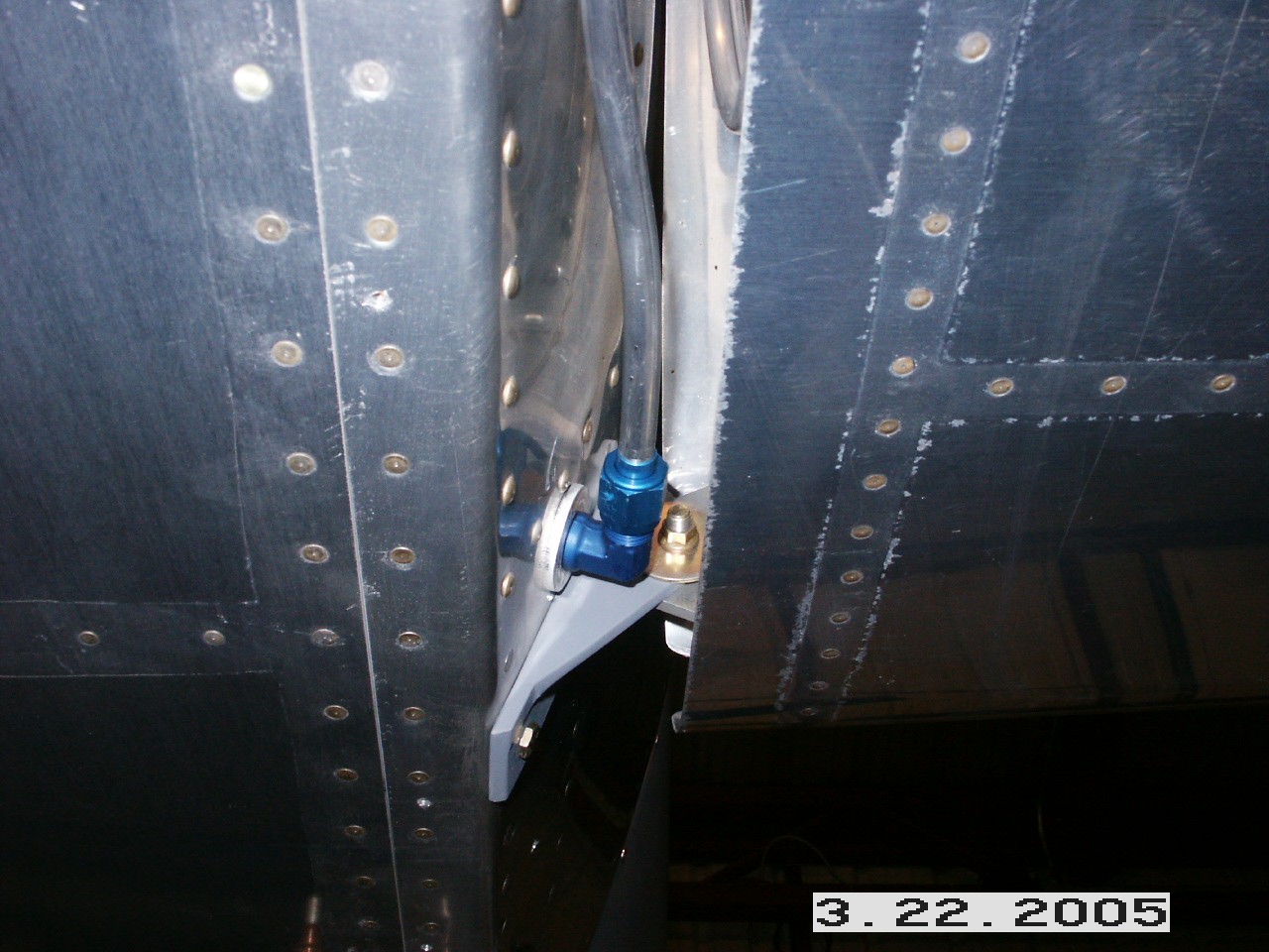
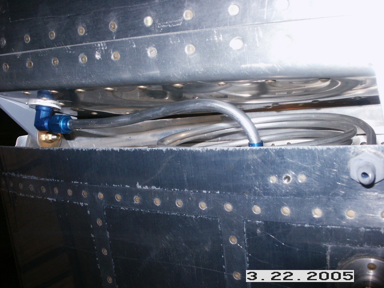
Here are the pictures of how I connected the fuel tank lines to the fuselage bulkhead fittings. My fuselage fittings are installed just forward of the fuselage bulkhead by your feet. That will give me a straight shot into the fuel valve. The right tank (left picture) is pretty straightforward. The left tank (right picture) is more tricky because of the flop tube installed in the left tank. I used a tubing bender to bend the aluminum fuel line tubing to duck under the tank attach fitting. It is close but the line is not kinked, nor does it touch anything so it should be cool.
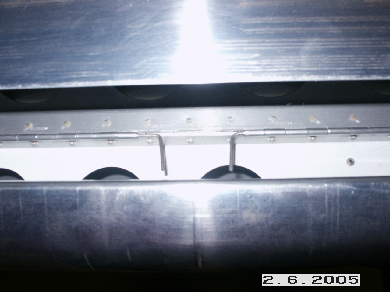
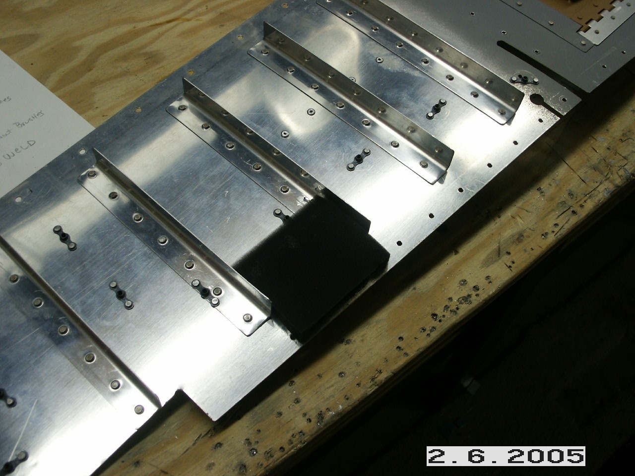
Following the procedures outlined in the manual, I trimmed the inside edges of the flaps. When mounting the flaps, I place the hinge pins on the inside, rather than on the outside.
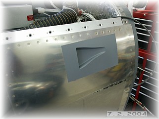
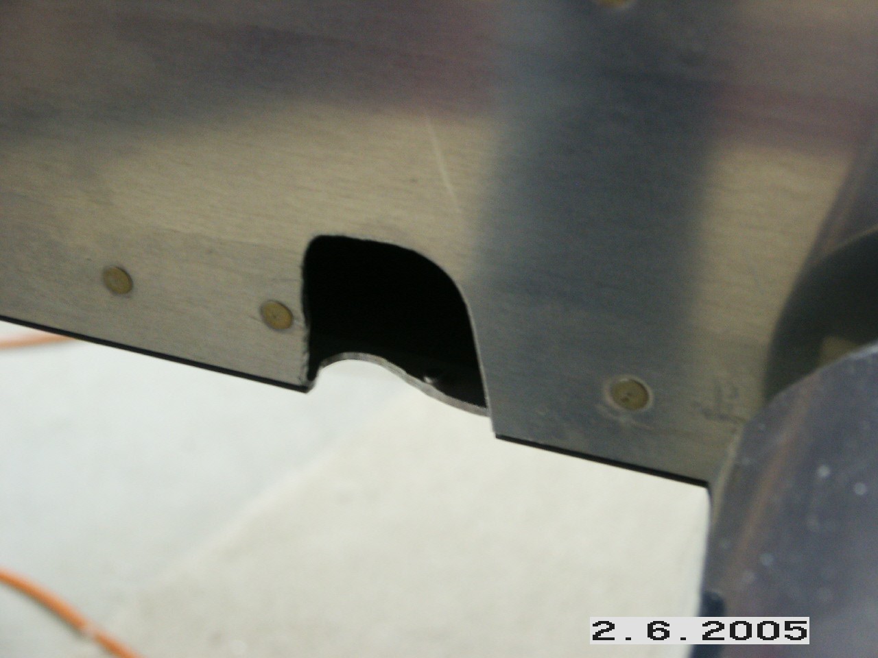
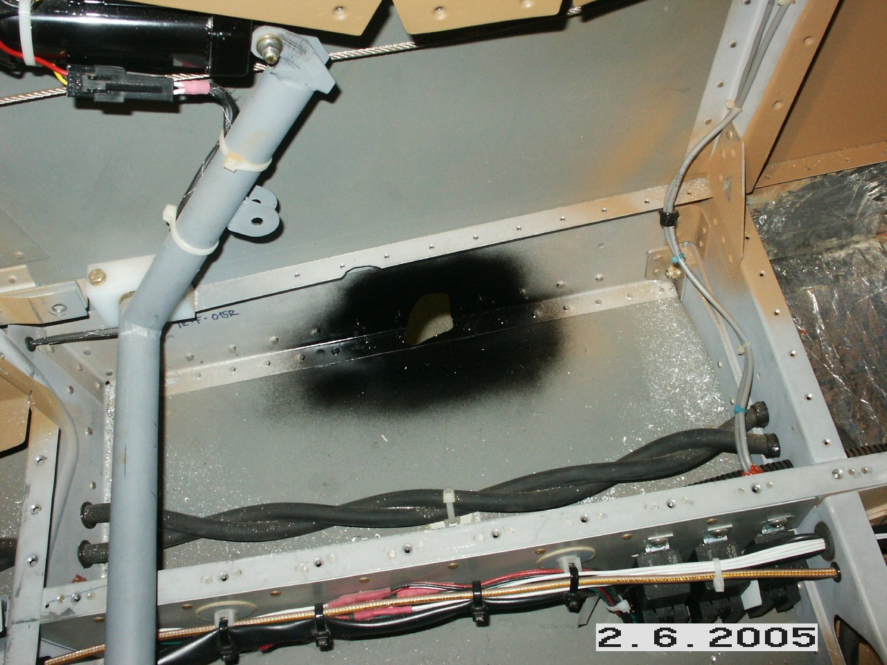
With the bearing mounted, I marked the outline of the opening and proceeded to make an initial cut. Then it was a matter of moving the flaps up and down and slowly trimming additional space around the torque tube. It took awhile, but I finally got a good fit. One hint for you. I had trouble with the tube hitting the side of the fuselage skin on the right flap. I took the bearing off the flap and added a couple of washers underneath it which moved the pivot point further towards the center of the ship. That fixed the problem. Once the opening was finalized, I painted the inside of the opening with black paint.
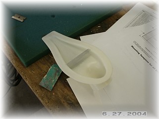
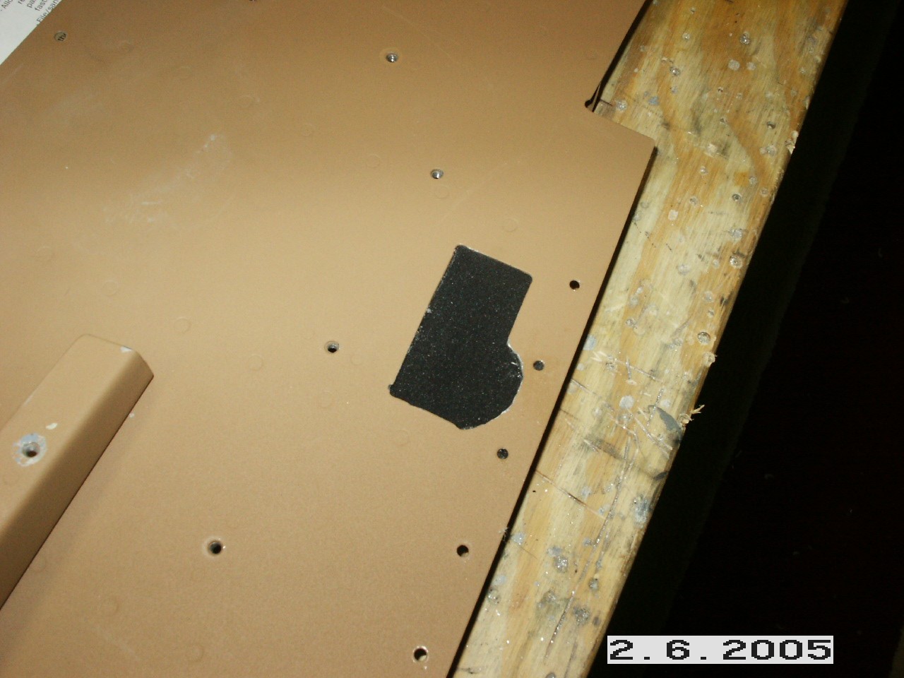
My floor openings are way too big. To help block the air from entering underneath the passenger seat pan, I used Vince's trick and bought a couple of cheap foam paint brushes, With a little help from a razor blade, I was able to separate the foam from the handle. I simply glued the foam over the opening. Once this dries, I will use the razor to cut a slice in the foam approximately in the center of the arm travel. That should keep the breeze down to a minimum. This area is hidden by my rear armrest panels, so no one will see it, but you'll sure feel the cold air if you don't do anything. I'm waiting for some parts that are on order to finish the flaps. I intend to add a piece of aluminum to the end to cover up the joint and the opening from the bottom. When the flaps are closed, there will be a seamless transition. I tried to make these parts out of some thinner aluminum, but I thought they might bend in the wind when the flaps were extended, so I'm waiting for some thicker aluminum.
I constructed the torque tubes according to the plans and connected them to the center stick. On my stick, I think the steel tabs for the aileron mounts were welded in the wrong place. They are not centered in the lightning holes of the ribs. When I moved the ailerons to their limits, the torque tube rubbed the ribs in two place. It rubbed the outer rib up at the top and it rubbed the inner rib at the bottom. Rather than disassemble the center control tub and re-weld the brackets, I took the easy way out and used my Dremel to enlarge the openings a little. It's ugly but it works. Next step is to mount the magnetometer in the wing tip. That work begins on the next page. |
||
|
|
||
|
"All that is gold does not glitter, not all those who wander are lost" - John Ronald Reuel Tolkien |