|
|
| Home-->F1 Rocket Project-->Wings Page 4 |
|
SITE CONTENTS
Please send your comments and suggestions to: Copyright
© 2002-2005 by
|
Links
on this page: Install Wingtip Lens Final Wing Tip Attachments |
|
|
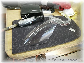
Install Wingtip Lens
I cut and trimmed the wing tip lens until I got a good fit. The lens is marked with the outline of the tip and I found them to be accurate. It took me almost two hours to trim, fit, trim, fit, trim, and fit the lens. I found that to get the best fit, hold the lens to the opening along the leading edge and then mark the high spots. Avoid final fitting the sides until you get a good fit along the leading edge. Otherwise it's too easy to kind of bend the lens out of shape slightly trying to force fit the other side. By following the contours of the leading edge, the lens will fit better.
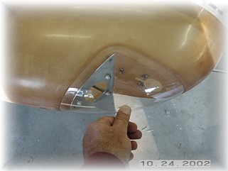
Once the lens was ready to attach, I finished the inside of the lens area. I first painted the area, then filled the imperfections with spot putty and painted again. The lens was installed with #4 countersunk screws and nut plates that I got from Cleaveland. They are the only one that I've found that carries them. The smallest that I could find elsewhere were the #6, which I think are too big for the lens. It was a real pain to rivet those small nut plates into the tip area. I spent several hours just fiddling with the fit of stuff and riveting on all those darn nut plates. I often drilled out the rivets holding on the nut plates if the resulting fit wasn't to my liking. I've seen two different ways to attach the tips. One is to rivet a strip of aluminum to the wing, and then trim the flange off of the fiberglass tip. This causes you to put the screws into the fiberglass part. The other way, and the way that I prefer, is to mount an aluminum strip to the underside of the fiberglass part and put the screw through the aluminum overhang on the wing. I like this better because it looks cleaner and puts the screw through the stronger of the two parts. Having built and flown a Long-EZ, I've come to avoid putting screws on the outside of fiberglass parts because eventually, the screw head will work its way through the part without a metal washer underneath it. Most folks don't use the washers because they don't like the way they look. I can't blame them but if the fiberglass part vibrates at all, the screw will eventually come through.
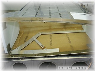
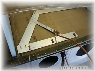
The first step is to cut some strips of aluminum from a scrape sheet I have laying around and drill it to the tip using the mounting holes. I then took the strips over to my bench and drilled them for nut plates. Before the nut plates are attached, I reattach the strip to the tip and enlarge the mounting holes to their final size. It is important to do these steps in a very specific sequence so that the holes in the wing will align with the nut plates in the strip and everything will look good.
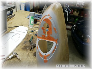
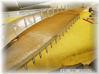
I drilled about six attaching holes in the strip and the tip for mounting.. After slathering on some Proseal, I riveted the strips to the wing flanges. I then mounted the wing tip to the wing to let the Proseal set up.
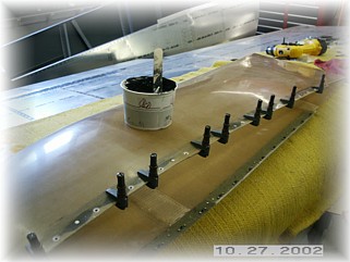
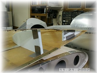
The tip is pretty flimsy even when it is fully attached to the wing. At over 250 mph, I'm concerned that the tip might flex and chip the paint. As a result, I decided to install a series of 4 foam ribs inside the tip. Here I am trial fitting the ribs. These will help the tip hold its shape.
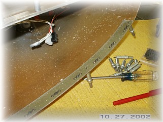
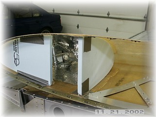
In between two of the ribs, I'm installing a Bob Archer NAV antenna. It is just sitting in the bottom of the wing in this picture. I will finish the install of the antenna later this week. Once I was satisfied that the ribs were the right size, I prosealed them in place and then attached the wing tip to the wing to let it set up and harden. Once the proseal is set, I will remove the tip and apply a couple of layers of glass to the ribs.
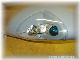
Once the proseal set up, I finished up the wiring connections to the NAV antenna. The instructions called for the inside strip to be well grounded in at least three places, so I used the supplied screws to ground the strip to the spar. I then reattached the tip and prepared it for sanding and filling.
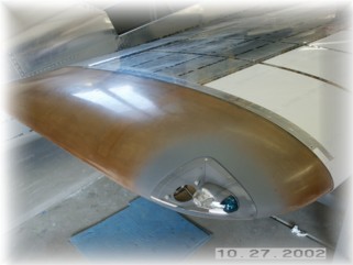
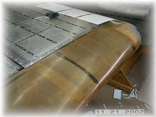
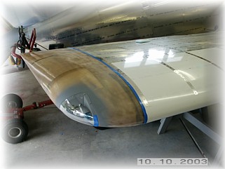
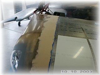
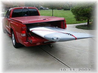
Using a dry mixture of microballons, I filled in the edges of the tip. I sanding everything smooth and primed the part. That finishes the right wing so I loaded it up and hauled it off to my hangar where it will patiently wait for the fuselage in a couple of months. The only construction details that are different on the left wing are the pitot tube and the NACA inlet. Those details can be found on the next page. |
||
|
"The only place success comes before work is in the dictionary." |