|
|
| Home-->F1 Rocket Project-->Elevators Page 4 |
|
SITE CONTENTS
Please send your comments and suggestions to: Copyright
© 2008 by |
Links
on this page: Assemble Trim Tab Wire Trim Tab Motor Attach Counterweight Tip Fairing |
|
| Assemble Trim Tab
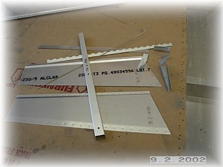
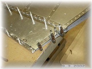
First step in getting the trim tab together is to gather all the parts. Per the plans, I drilled and riveted the hinge to the trim tab spar in three spots. I didn't overset these rivets since they will be drilled out and replaced after all the skin holes are drilled.
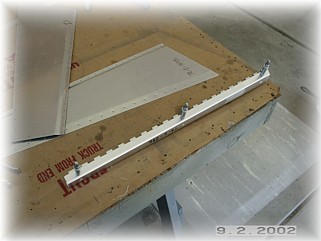
With the spar pinned to the elevator, I aligned the skin with both the trailing edge and the inside edge. Once I was satisfied that everything lined up good, I drilled the skin to the spar and through the hinge.
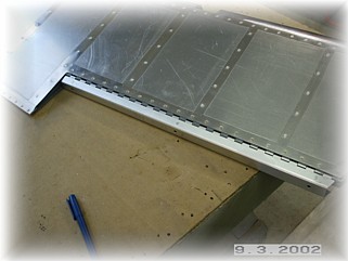
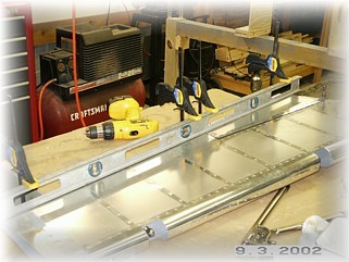
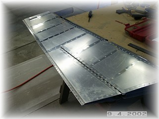
The rest of the skeleton can now be assembled and drilled to the skins. The bottom skin is attached after the top skin and skeleton assembly is pinned level with the rest of the elevator. This is one of the most important steps in get right in order to have a nice looking tab. Once you have the trim tab pinned in the same plane as the elevator, carefully turn it over and drill the bottom skin to the spar.
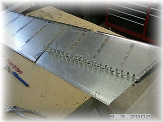
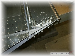
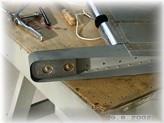
The final drilling detail is to align the hinge parts over the end rib before drilling them together. It is important to get the hinge point the proper distance behind the spar, per the assembly manual. I had to trim the forward edge of the small hinge part because it was too long. It is important to get this measurement correct otherwise when it's all assembled, the push rod will bind in the opening before the tab travels the full distance.
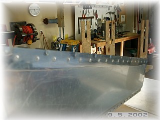
After cleaning, dimpling, countersinking, and priming the parts, I reassembled the spar and the hinge. I riveted the spar first, the end ribs next, and finally the trailing edge. Here it is all assembled and pinned in place.
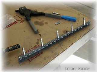
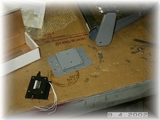
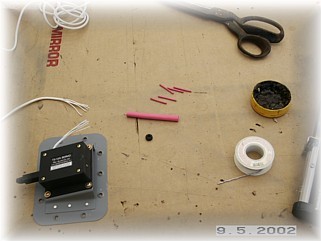
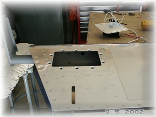
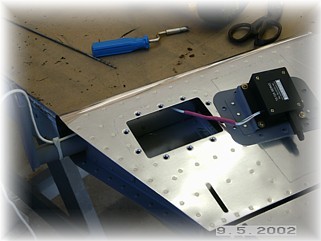
Finishing up the trim tab means installing the servo and making all the necessary wire connections. There are any number of ways to attach the trim motor to the mount. I used some small screws and locking nuts that I had. When I attend fly-ins, I usually peruse the fly markets looking for small screws, nut plates, and other small attaching hardware. It seems I always have a need for these kinds of parts.
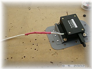
If you haven't done so already, order yourself about 20' of five conductor wire from the Ray Allen Company. It is smaller and more convenient for wiring up the trim motors than using 22 gauge wire. I solder each wire together, covered by a small piece of heat shrink. I then cover that whole assembly with a larger piece of heat shrink.
In the back of trim motor opening, you'll see a small hole with a grommet in it. This is located just outside the steel paddle from the control horn. I pass the wires through this grommet and down to the horn. There, I hold it to the horn with a tie wrap. When the horizontal stabilizer and elevators are installed on the fuselage, this wire will run up over the top of the horizontal stabilizer spar, underneath the empennage fairing.
One last detail that I do is to bend the rear edge of the trim tab down slightly so I know it won't bind up against the elevator spar. Since the skin tends to get a little wavy, I put a series of flutes along the edge to really tighten the skin up.
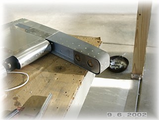
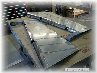
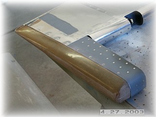
All that is left is to bolt on a set of my pre-molded empennage weights.
And with that, the elevators are finished except for the tips.
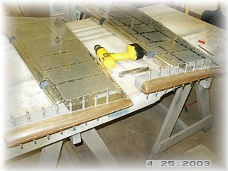
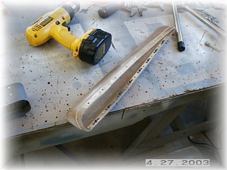
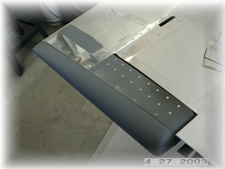
First step is to drill the fairings to the skin using holes that are 2" apart. I then installed an aluminum strip and platenuts since that is my preferred method of attaching tips. I also used my Dremel tool with a drum sander on it to clean up the flange on the parts.
I trial fit it once the platenuts were completed. Then it was back to the bench for three rounds of sanding, filling, and priming until I got all the pin holes filled. That completely finishes the elevators. They are now ready for final priming and finish paint. |
||
|
"Genius
is nothing more but a great aptitude for patience." |