|
|
| Home-->F1 Rocket Project-->Rudder Page 1 |
|
SITE CONTENTS
Please send your comments and suggestions to: Copyright
© 2002-2005 by
|
Links
on this page: Attach Stiffeners Assemble Skeleton |
|
|
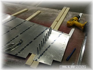
Attach Stiffeners
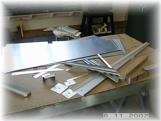
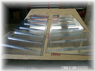
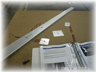
First step in building the rudder is to get all the parts together and determine which pieces of stiffener go with the rudder and which pieces go with the elevators. I laid out all the skins and then fiddled with the stiffeners until I had them placed with the right skins. It looks like I'm short one piece of stiffener so I'll have to give Mark a call.
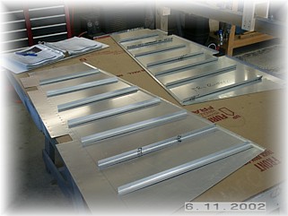
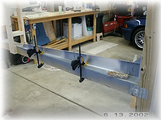
With the stiffeners laid out on the rudder skins, it's time to trim them up and polish their edges. Follow the directions to get the right dimensions. Care must be taken to ensure the proper alignment so that the stiffeners will not interfere with one another when the two skins are joined. On the right-hand skin, the stiffener angle is toward the top. On the left-hand skin, the stiffener angle is toward the bottom.
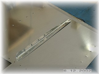
Drilling the stiffeners to the skin is accomplished with the skin upside down and the stiffener held between two pieces of wood. Mark the centerline of the stiffener and draw an intersection point about 1/4" in from the fat end of the stiffener. The centerline should be slightly off center towards the web to provide adequate overlap of opposing stiffeners once the two skins are joined. Place the stiffener between the wood blocks and lay the pre-punched skin on top. Make sure you have the outside of the skin on top and the inside of the skin towards the stiffener. Locate the intersection point in the first hole and drill it. Then align the centerline in the rest of the holes and drill them to size. Do this for all the stiffeners on both skins. Clean and dimple the skins and the stiffeners.
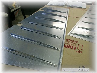
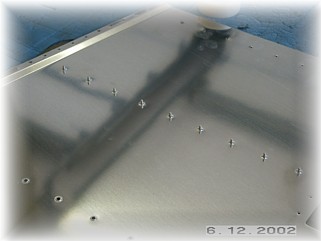
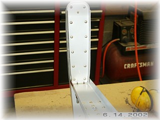
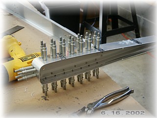
Riveting the stiffeners is, at the same time, some of the easiest riveting AND the most dangerous riveting. These skins are very thin so they won't take much abuse from a bad day with the rivet gun. Tape of row of rivets in their holes and place the skin down on your rivet backing plate. Make sure your skin is supported all around the plate or you WILL crease your skin. Place the stiffener over the rivets and use your back riveting set to set these rivets. VERY LITTLE PRESSURE is needed. Don't get too overzealous with the gun or you will over set them. I first set about every fourth rivet to avoid any forced creep of the stiffener. I then go back and hit the ones in between.
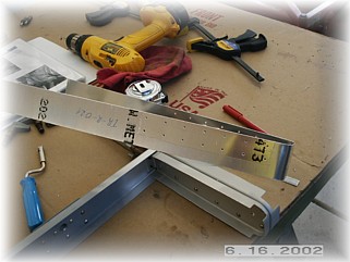
With the stiffeners in place, I'll put the skins aside and assemble the skeleton.
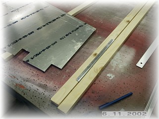
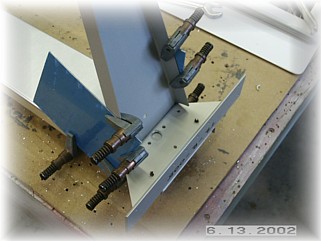
The first
step is to align and drill the reinforcing plates to the spar. The
top two are attached on the aft face of the spar. The bottom plate
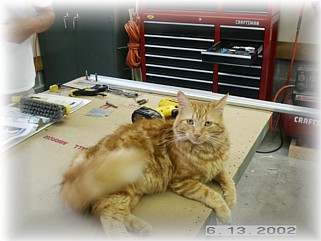
is attached to the forward face. Be sure to not drill the cat's tail
when working on the assembly.
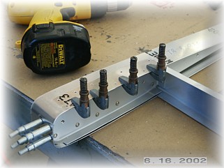
Drill and cleco the bottom rib and attachment angle. This area is not real clear in the plans. The web of the rib goes behind (underneath) the angle. A spacer must be fabricated from scrap to fill the remaining area underneath the angle. These are then drilled together with the reinforcing plate, which can't be seen because it is on the other side of the spar.
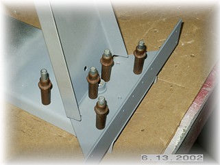
Rivet the spar parts together. Drill and cleco the two top ribs per the plans and rivet them together. I didn't see in the the plans when the tips should be riveted on. I think they want you to wait so that you can maximize your adjustments of the skin in relation to the tip of the vertical stabilizer. I've found that if your rivet everything on, making sure that the web of the rib is perpendicular to the spar web, this will fit just fine. I can always adjust the gap by trimming the top skin of the vertical stabilizer, which I left long for that purpose.
I pre-drilled the tip skin. After drilling the skin to the end of the tip ribs, I then clamp the skin back and drill towards the aft. Care must be taken to ensure that the rib is square to the spar, especially when the last hole is drilled, the one into the spar and through the tab of the rib. As the plans state, don't drill any holes further aft than the spar since the skin is pre-punched in this area.
This is as far as I can take the tip skin at this point. Next is to prep the skins prior to mounting them in the jig for drilling to the skeleton. I'll start on that this coming week. |
||
|
"If
man could be crossed with the cat, it would improve man but deteriorate
the cat." |