|
|
| Home-->F1 Rocket Project-->Fuselage Page 1 |
|
SITE CONTENTS
Please send your comments and suggestions to: Copyright
© 2008 by
|
Links
on this page: Empennage Deck Rudder Cable Slots Rear Baggage Floor |
|
|
Now that I have the quick build fuselage sitting in my shop, it is time to stop admiring it and time to go to work on it. I've spent a little bit of time thinking about my strategy for working on the fuselage because with a project of this complexity, there are many paths that will take you to your destination. Also, it is not uncommon for work to come to a grinding halt while waiting for parts to arrive. So my strategy is this. I will generally follow the steps outlined in the manual. At the same time as I am working on the fuselage, I will also work on the wings and finish the empennage fiberglass parts. Once I get a little further down the road, I will likely divert from the steps in the plans.
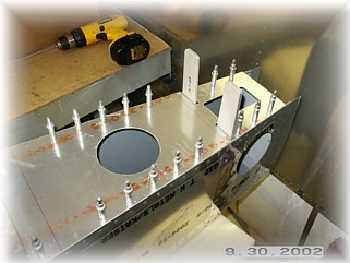
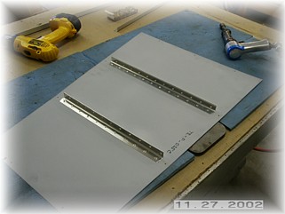
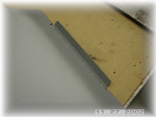
The very first step is to finish drill the F-019 deck to the fuselage. I drilled through the pilot holes in the part with a #40 drill and drilled it to the longerons. I then marked the centerlines of the cross pieces and drilled those holes as well. Once all the holes were drilled, I drilled the holes up to their final size (#30), cleaned, deburred, and primed the parts. Final riveting is done at a later point in so that I can still get my fat hands down into this part of the fuselage. The only real trouble area here is to avoid putting rivets in any area where you will eventually drill attachment holes for the horizontal stabilizer. These locations are depicted in a picture in the manual, but no dimensions are provided.
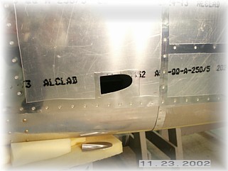
Personally, I don't care for the look of the
slots just cut into the side of the fuselage. By my estimate, that
should cost you at least .2 knots of airspeed!
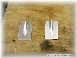
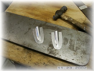
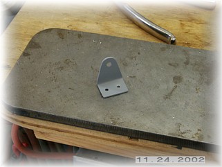
I ordered a set of cable fairing from Avery. You get three of them in a package. The first step is to trim them to the desired size. I left an even area all the way around, just enough for the mounting screws. Be sure to mark a left and a right one when your done.
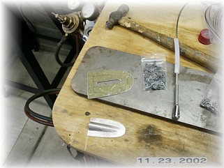
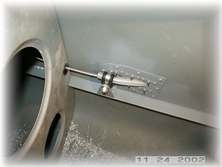
Next I cut holes in the side of my fuselage using the fairing as a guide. That's why it is important to mark both a left and a right fairing so the holes will match each part closely. I had to place my opening a little higher than the dimension called out for in the plans in order to have enough room to rivet on a reinforcing ring. It won't really make any difference in the operation of the rudder. I used some scrap to fabricate a reinforcing ring. In the middle of the ring I cut a slot for the plastic cable tubing. The slot ends just a little short of the end of the fairing so that the plastic tubing will be squeezed by the fairing when it is screwed in place.
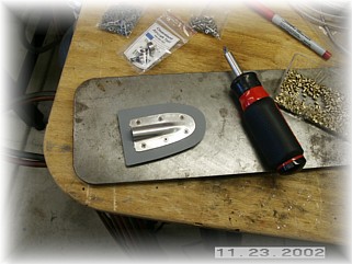
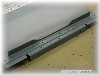
After a bunch of drilling and riveting, I screwed the fairing to the reinforcing ring. I then positioned the ring in the skin opening so that I could center the fairing in the opening evenly. I then drilled the attach holes through the skin and ring. After cleaning and dimpling, I riveted the ring in place.
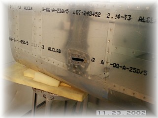
On the inside, all that was left was to make an attachment for the -6 hose clamp to secure the end of the plastic tubing. I made a couple of L brackets from scrap and riveted them to the longeron. I used a nut and bolt to hold the clamp to the bracket.
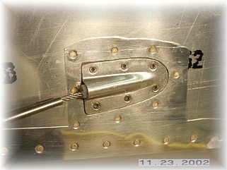
When I was all done, this is what it looked like. Now I like that much better than just a slot.
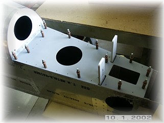
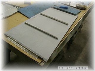
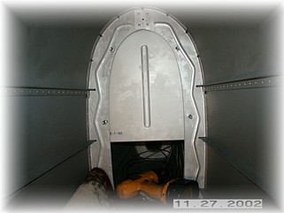
The first step is to rivet on the reinforcing ribs to the bottom of the baggage floor. I riveted the two middle ribs using the backing plate.
The front and rear ribs are a little different. The front one is made up of a piece of .063 angle riveted to a piece of .040 formed angle. The formed angle point forward and will be used to join up the next baggage floor. This is per the plans. Based upon some advice from fellow Rocket builder Tom Martin, I modified the rear angle to be different from the plans. I first riveted the .063 angle to the rear bottom of the skin as shown. Actually it is a little too close to the rear edge of the skin. If I were to do this over, I would leave it about 1 inch forward of the rear edge.
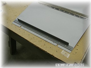
Next, I riveted on a piece of bent angle as shown above. This will be used to attach the floor to the rear baggage close-out panel, which I mounted next. You need to trim the aft edge of the floor panel so that the angle, once mounted, will rest flush with the forward surface of the rear close-out panel. Notice that I also trimmed the lower edge of the angle. This is to ensure that I have sufficient clearance for the elevator torque tube, which passes very close to this angle once the elevators are mounted and the torque tube is attached.
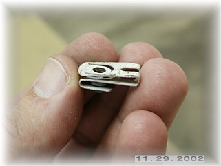
Instead of mounting the close-out panel per the plans, I mounted it up against the aft edge of the bulkhead and drilled four attach holes. I then removed the close-out panel and mounted nut plates to the aft close-out panel in these locations. Also, save yourself a bunch of headaches, and buy yourself a couple of dozen of these clip nuts. It is much easier to drill the attach holes in the longeron and clip these over the holes rather than try and mount nut plates to the longerons. I had enough trouble just getting the mounting holes drilled. I can't imagine fighting to get the nut plates drilled and riveted.
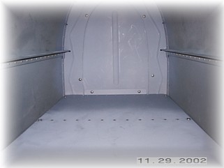
After cutting slots for the attaching screws in the edges of the baggage floor panel, I installed the floor. This is what the finished rear baggage floor and close-out panel looks like. Next step is to mount the remaining two baggage panels. That begins on the next page. |
||
|
"You
can lead a man to Congress, but you can't make him think." |