|
|
| Home-->F1 Rocket Project-->Rig/Final Assembly Page 10 |
|
SITE CONTENTS
Please send your comments and suggestions to:
Copyright © 2002-2005 by |
Links
on this page: Mounting the Magnetometer Upper Gear Leg Fairing Wing Root Fairing Fuel Pump Assembly |
|
|
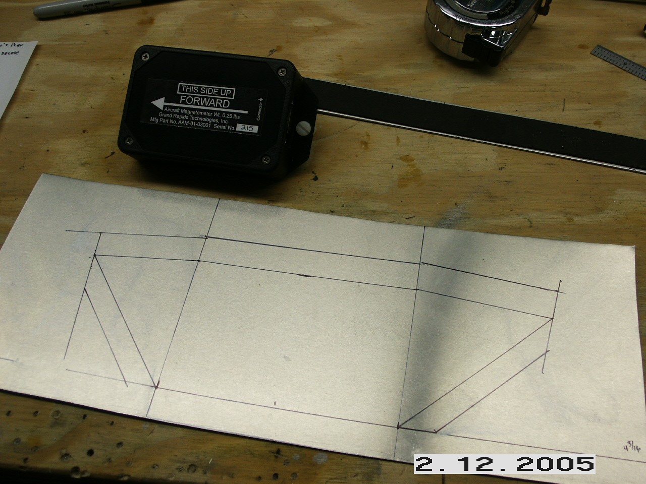
The EFIS unit requires that the magnetometer be mounted out in the wing tip. When installed, the magnetometer must be level in roll and pitch when the airframe is leveled. I laid out a bracket on some aluminum, cut it out, and riveted it to the outer rib of the left wing.
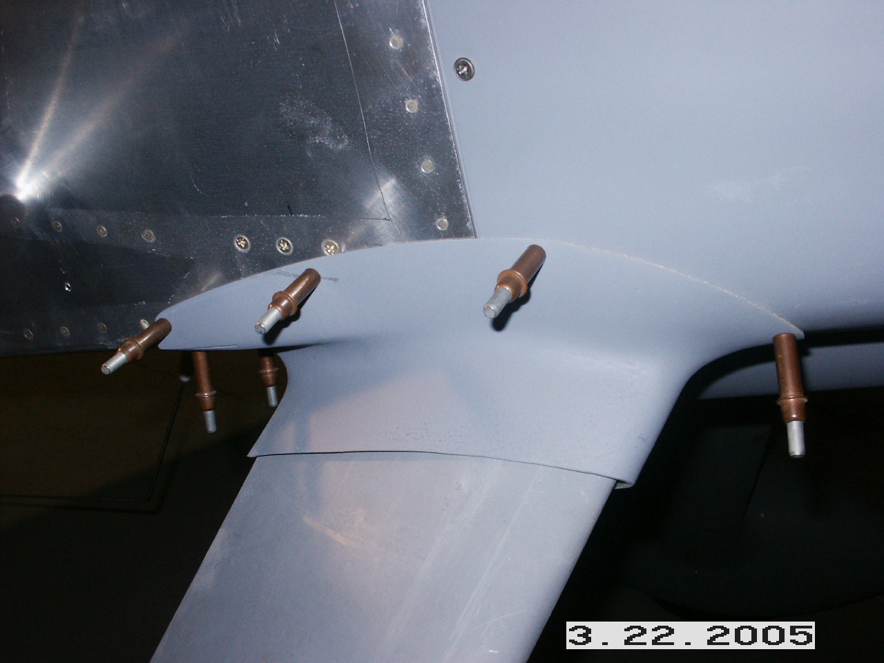
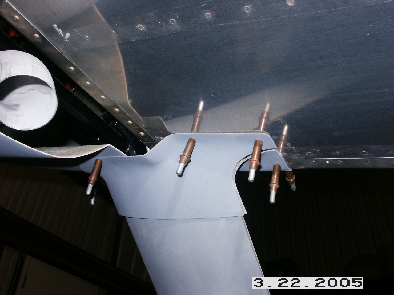
Here are a couple of shots of the upper gear leg fairing. I used them just as they came from Team Rocket and they fit pretty good. I split mine along the trailing edge. When I get around to finishing these, I'll fill the gap at the trailing edge and sand it smooth for a clean, thin line.
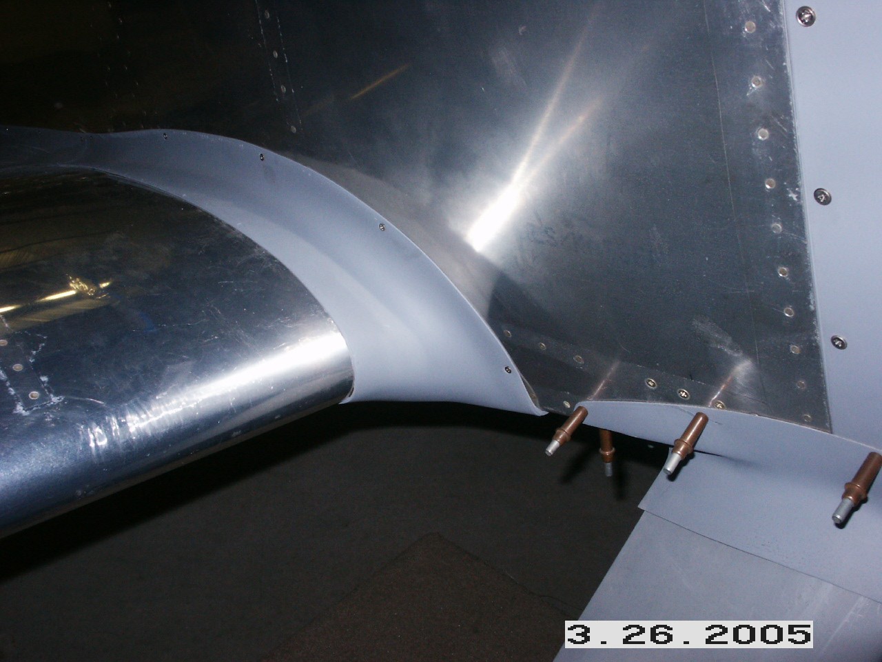
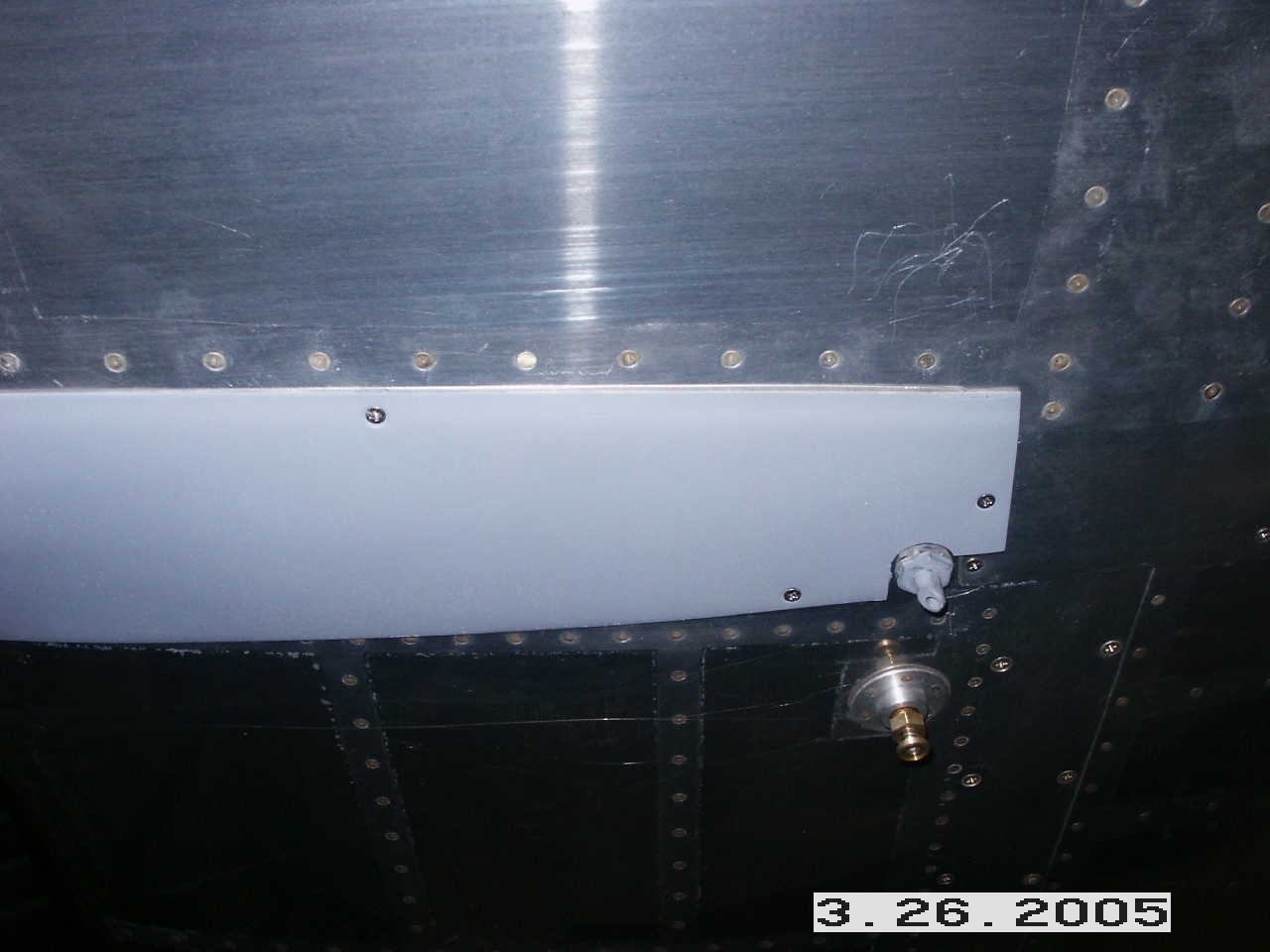
I went ahead and mounted the forward piece of the wing root fairing. These too went on right out of the box with very little fitting and fussing. I have some small gaps to flox later on, but for now they will be sufficient. Since I already had my leather interior panels installed, I went ahead and used nutserts in place of plate nuts. I don't really care for the things all that much but they saved me from destroying my interior.
Here's the rear piece of the wing root fairing. This has more gaps than the front piece so it will require a fair amount of finish work to get it up to standards. Overall the fit isn't bad.
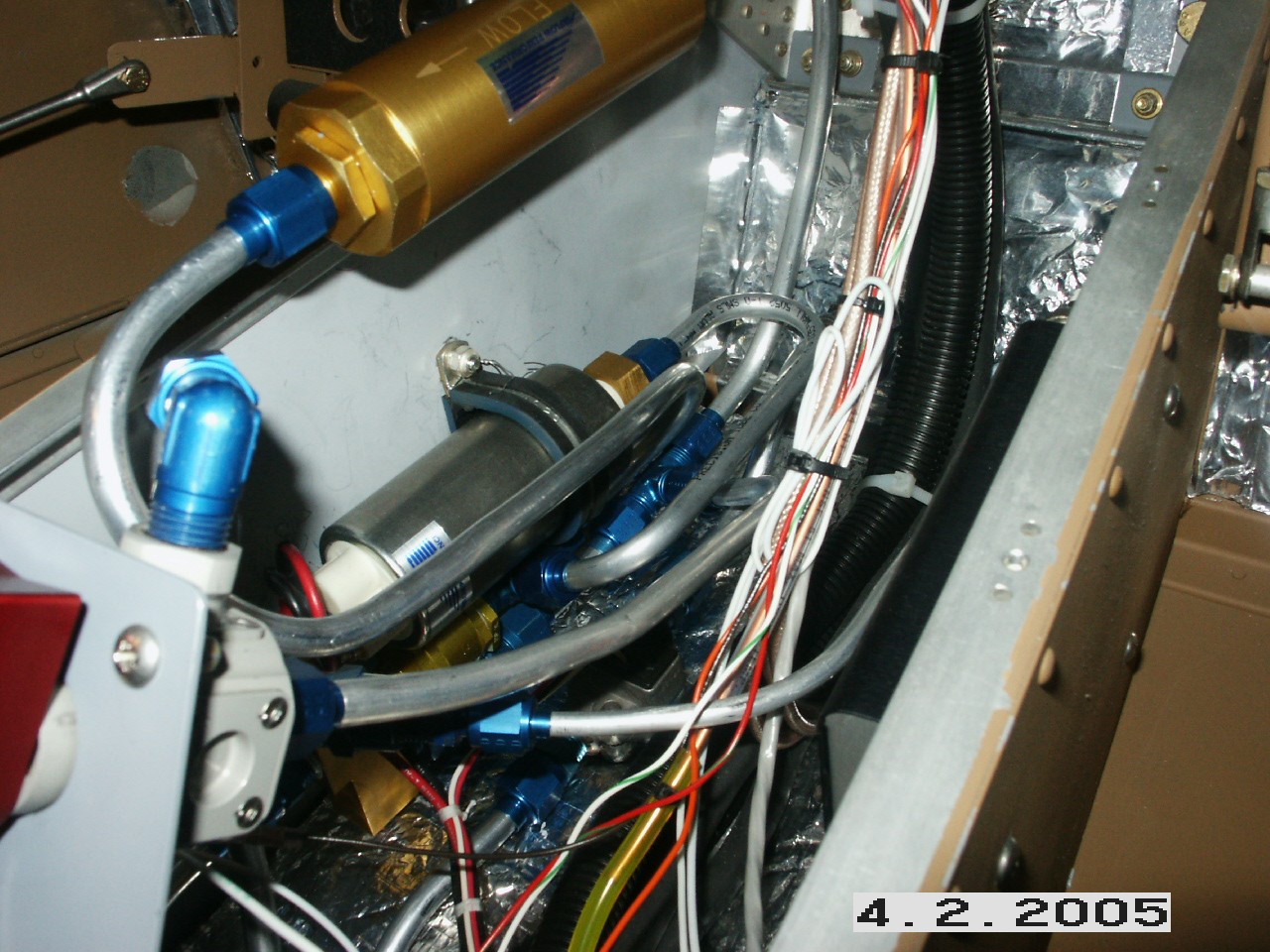
I installed my electric fuel pump, fuel flow controller, and filter in my center tunnel AFTER I had everything else done. I wouldn't recommend following my lead on this one. It was tough to get everything to fit in those tight quarters. I did manage to fit the pump and flow controller as one assembly so it can be removed by removing two hose connections. The pictures show the filter assembly on top, but it doesn't show the supporting brackets. I removed them for clarity. This will all be covered up but the filter is more easily accessible since it sits up higher, but still under my cover.
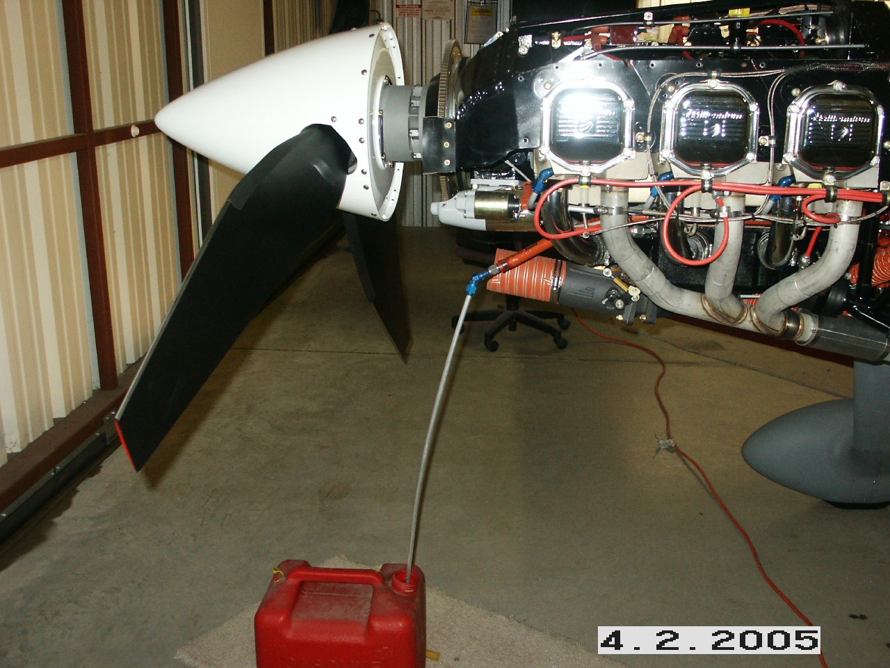
The next step was to check for leaks and to flush out the tanks and hoses. I put 5 gallons of fuel in the left tank and then pumped it out, back into the gas can using the assembly pictured above. My fuel flow meter showed a flow of 47 gallons per hour. I then repeated the process in the right tank. Fortunately, I haven't found a single leak in the system so I am VERY happy. Now all I have to do is start bolting everything back together. That concludes all the Rig/Final assembly steps. |
||
|
|
||
|
"Nobody who takes on anything big and tough can afford to be modest." - George Orson Wells |