|
|
| Home-->F1 Rocket Project-->Engine Page 1 |
|
SITE CONTENTS
Please send your comments and suggestions to: Copyright
© 2008 by
|
Links
on this page: New Mount Mount the Mount Gear Legs/Wheel/Tires |
|
|
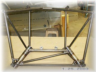
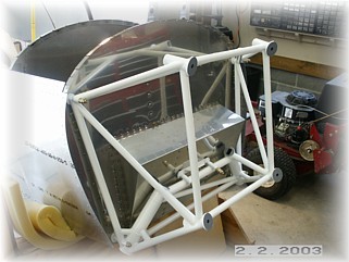
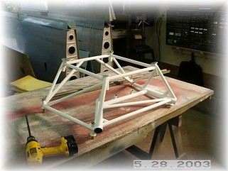
This weekend, I picked up the new engine mount that the Indy gang designed. After fellow Rocket builders Jim Winings and Bob Japundza looked at the current mount, they decided to do a little reengineering. They found a shop in Speedway that fabricates race cars and had them put together a jig.
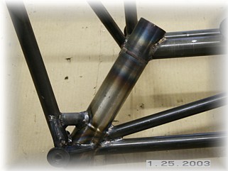
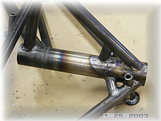
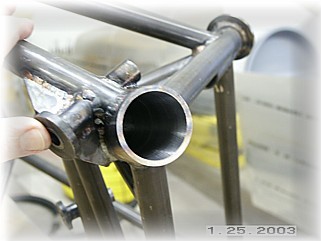
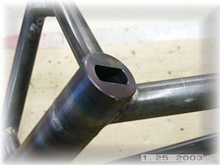
There are a number of important changes between this mounts and the old Mk 1 and Mk 2 mounts. The most important change is in the gear sockets. These are custom machined and are twice the thickness of the old sockets. They are reamed and honed after welding to ensure a taper that is true. Other changes include thicker and larger tubing in certain places, tubing gussets instead of plate gussets, and a few others changes. All I need to do is bolt it up. No further machining is required.
I trial fit my gear legs and they fit perfect. This mount is really a piece of art. The welding is first class and it appears that the engineering changes may help to prevent the mount cracking that has occurred on other Rockets. We won't know for sure until we fly them for a couple of hundred hours but I can't imaging that these will be worse than the current mounts. Jim and Bob did all the leg work on this and they deserve all the credit. I am just lucky to benefit from knowing them. If you have any questions about the mount, contact Mark at Rocket headquarters. At this point, the Indy mount is now supplied with all new kits that are ordered from Team Rocket.
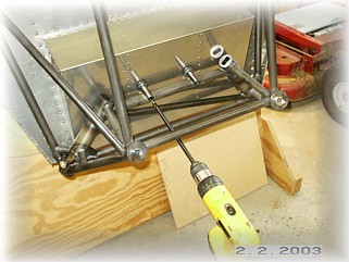
To attach the mount to the firewall, I first drilled the pilot holes up to 1/4" and attached the mount with some hardware store nuts and bolts. The bottom holes fit okay. However the top two were just a little bit off. I did manage to pull the mount into shape in order to get the bolts in, but it will just spring back once they are removed.
I then drilled the bottom holes one at a time up to 3/8" and installed the proper bolts and nuts. I then did the top two in the same manner. When I had the four corners secured, I noticed that the center mounts are away from the firewall by about 1/8". I'll deal with that in a moment. Right now, I used a 12" long drill bit to reach the center mounting holes. On this mount anyway, the center mounts are just low enough so that I could get the bit in without bending it at all.
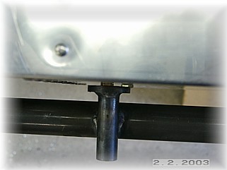
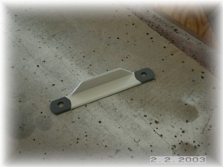
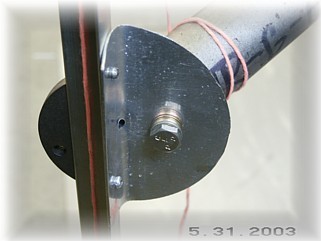
To deal with the gap in the center mounts, I went ahead and fabricated a spacer out of 1/8" angle. I used angle because that's what I had in stock. The right photo shows the spacer installed on the firewall. The bolts are just temporary until I can order some that are the right length.
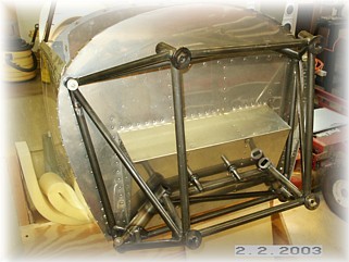
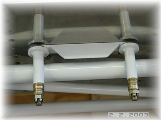
This is what the mount looks like all bolted up. I will have to remove it to rivet the firewall to the skin and to install the gear legs so it is just temporarily bolted up for now. I did measure for the correct bolts and will order them when I send in my next parts order. AN6-31 bolts are the proper length needed.
To set the proper toe-in, I bolted the engine mount to my table and leveled it both left and right and up and down. I used the mounting pads on the attach tubes to level the mount. You have to be careful what you use. You can't rely on any of the tubing and the engine pads are set up so that the engine points a little to the right to counteract the engine torque and P-factor.
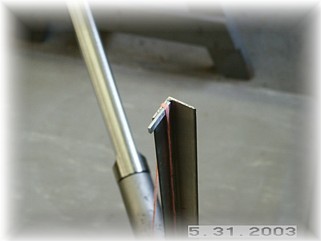
Instead of using a board per the instructions, I made up a very simple jig to set the toe-in. I took a straight piece of angle and cut it TWICE as long as the plans indicate. In the middle, I riveted a small piece of angle and drilled a hole in it to fit the screw hole in the bottom of the gear leg fitting. At the top of the angle, I cut a small piece of .064 plate and glued it to the end.
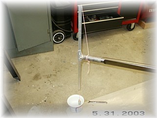
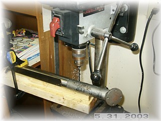
With the jig bolted to the lower gear fitting, all I had to do was drape a plumb bob down the angle and then turn the gear fitting until the string just touched the bottom edge. After marking the location of the fitting, I removed the gear leg and took the entire assembly over to the drill press for drilling per the instructions.
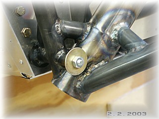
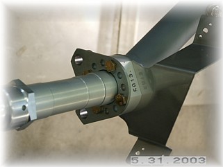
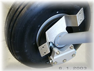
Once everything cooled off, I removed the fitting, cleaned up the holes and primed the fitting before attaching it. With both of them done, it was time to bolt up the axle, brakes, and wheel pant fitting. I have the Grove brakes and this is the way that things bolt up for them. This picture was taken after I trail fit everything. Later, I removed the bolts and placed a washer underneath the bolt heads while tightening the bolts down with some Lock-tite.
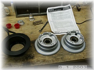
Over on the bench, I split the wheels in half and packed the bearings with grease. Using the instructions that came with the brakes, I assembled the wheel and tires.
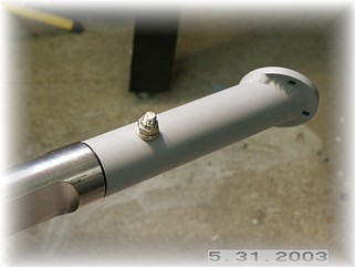
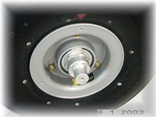
Unfortunately, either the instructions are poorly written or I'm an idiot. The Grove Wheel instruction say to mount the valve stem "opposite" the red mark on the tire. I think what they really mean is "adjacent to" or "aligned with" because the valve stem should be opposite of what is shown on this picture. After this picture was taken, I disassembled the wheels and tires and rotated the rubber and tube 180 degrees. The next step is to mount the wheel pants. That work begins on the next page. |
||
|
"Any fool can criticize, condemn, and complain, -- and most fools
do." |