|
|
| Home-->F1 Rocket Project-->Engine Page 5 |
|
SITE CONTENTS
Please send your comments and suggestions to: Copyright
© 2008 by
|
Links
on this page: Mount Engine Alternators Prop Governor Exhaust Heat Muffs Engine Wiring |
|
|
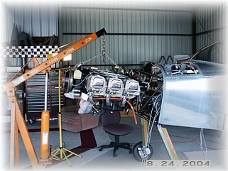
Mounting this engine is pretty easy. I just hoisted the engine into place and then lowered or raised the tail to match the engine "ears" Once it was in place. I inserted the rubber pucks and bolted it down. Remember to follow the instructions for the pucks. One puck is ribbed and goes in a different place top and bottom than the other, thicker puck.
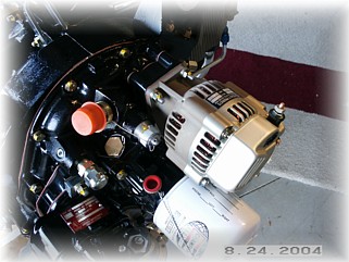
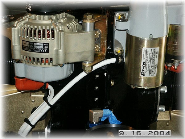
With the engine mounted, I began to mount the various accessories. First, I mounted my backup alternator to the vacuum pad. I also put a cover on the tachometer drive and safety wired it down. I then mounted my primary alternator to the front using the boss mount that came with the alternator. Both of these alternators are B & C products and they are top of the line. They will last longer than the engine. If folks want to goof around with automobile alternators, internal regulators and the such, be my guest. I like to fly, I don't like to repair. These alternators will go several THOUSAND hours. Just my preference, your mileage may vary.
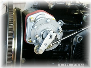
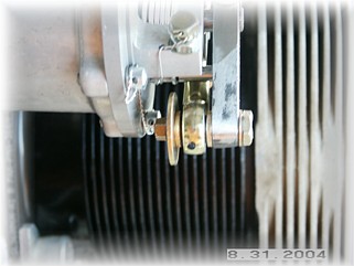
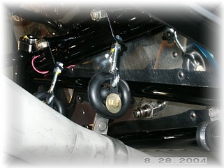
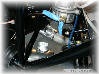
Up front, I mounted the propeller governor. This was just an easy bolt-on. The governor that Mark sells has a fairly thick flange on them. If you have the standard studs in your block, they will be too short. I had Bart install longer studs in my engine to take care of that problem for me. Out of the box, the control arm is clocked in the wrong position for our ships. I removed the six cover screws and rotated the cover until the arm was in the 7 o'clock position. The right picture shows my attaching hardware for the control cable.
Based up pictures provided by Mark and my Tom Martin, I fabricated the cable attachment bracket shown out of some scrap .062 aluminum. A simple hardware store U-clamp secures the cable to the bracket.
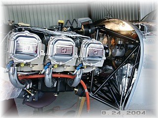
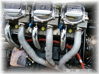
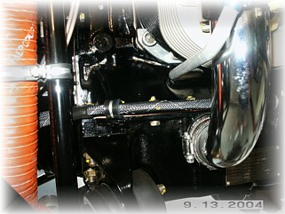
The exhaust system was another easy bolt on. The trick is to install the short tubes into the longer tubes and then bolt the entire side on at one time. If you try to do it separately, it won't work. The hangers were installed per the plans and look pretty sturdy. They should hold up fine, not like the original ones I had on my RV-6.
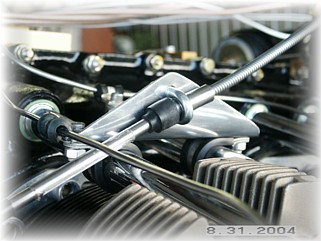
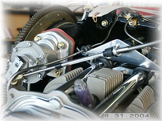
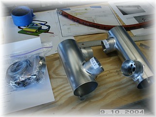
Here are the custom heat muffs that I had Rick Robbins make for me. They are 2" muffs of different lengths set up so that I can connect them up in series. I had him weld the inlets and outlets at the correct angles so the hoses don't interfere with the mount and the wiring. Air comes into the left muff, travels forward and crosses over to the right muff. Then the air travels down the right muff and up to my heat box.
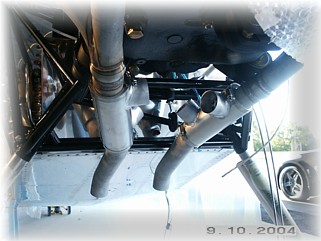
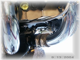
As you can see in the picture, the inlet and outlet are angled up to come up behind the engine. The picture on the right shows the SCAT tubing connected to the heat box. I don't have the inlet connected yet. I will need to wait until I have the baffles installed.
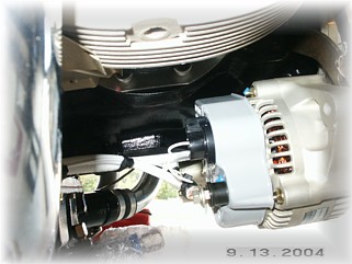
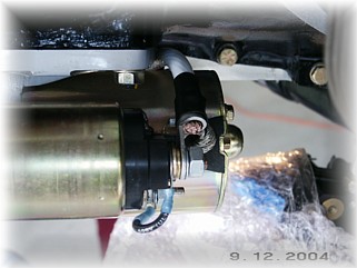
I located the exit point of my primary power wires down low on my firewall so that I could run the loom across the right bottom of the engine case. There, I installed a couple of clamps to the case bolts to point the wires at my primary alternator.
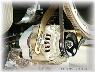
The alternator wiring was pretty simple as the wires easily are located in a non-stressful location. These pictures do not show the terminal boots installed. I have them on-order. I thought a lot about the starter wire. I ended up running the wire up under the case and around the top of the starter. This resulted in the shortest wire run and the best support. I used one of the mounting studs on the starter as a location for a cushion clamp that holds the wire off of the engine case. Again, the boot is missing in this picture but will be installed later when my parts order arrives.
Here's a picture from underneath looking up with the boots installed.
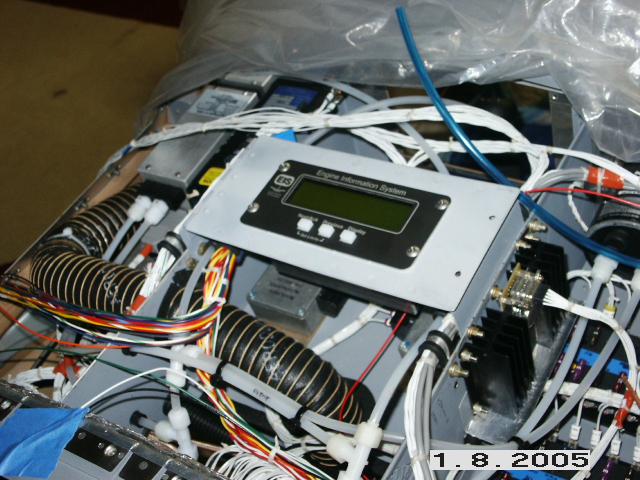
I finally got around to mounting my engine monitor. Since I don't need to install this in the instrument panel, I mounted in the center of the boot cowl area. It's not needed in the panel because the EFIS display will take its place. A serial output from the monitor drives the EFIS display, so this unit can go behind the panel. I made a flip up tray and routed the wires forward. |
||
|
"Furious activity is no substitute for understanding." |