|
|
| Home-->F1 Rocket Project-->Engine Page 4 |
|
SITE CONTENTS
Please send your comments and suggestions to: Copyright
© 2008 by
|
Links
on this page: Brakes Pick-up Engine Firewall Prep |
|
|
With the mount back on the airframe, I tightened and safety wired the gear leg mounting nuts. If you haven't already, you will need a crows foot wrench to fit the nut. Once the engine and accessories are mounted, you won't be able to get any other wrench on the nut, and these need to be checked for proper torque on a regular basis.
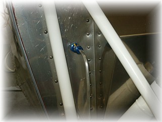
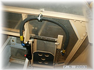
With the gear on for what I hope is the final time, I went ahead and ran the brake line. I had to remove the tire in order to have enough room to push the 1/4" tube up inside the 3/8" tube that I glued to the back of the gear leg. At the bottom, I wrapped the tubing along the bottom and around the front of the axle, This allows the brake line to ride inside the wheel pants and provides enough flexibility to allow the brake cylinder to move back and forth. At the top, I ducked around the back of the engine mount and up the face of the firewall.
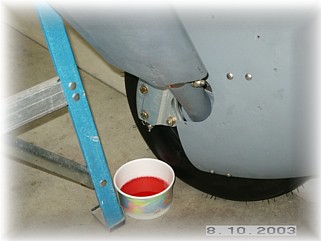
You can see in the pictures where I drilled the hole for the brake fitting. I figured that this is out of the way and in an area that won't be used to mount anything else. I made up some hose and secured it at the top with a cushion clamp.
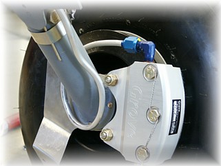
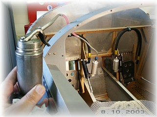
I decided to mount individual brake reservoirs directly to the brake cylinders instead of mounting one on the firewall. I like this better than drilling another hole in my firewall. I used the reservoir provided in the kit for one brake, and ordered another one from Wicks. Once mounted, I rigged up this homemade bleeder system using an oil can. As the plans indicate, I just pumped fluid through the system until no more air came out the bleeder valve at the caliper. The key to getting this to work is that your brake system must be air tight from the pump to the bleeder valve. Also, I bled the cylinder with it disconnected from the brake pedal. That way I can lay the cylinder on it's side which prevents any air from getting trapped inside.
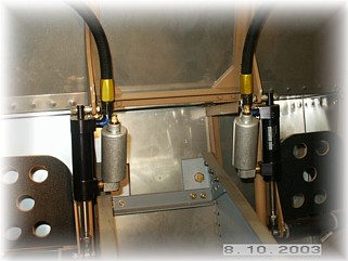
This is what it looks like when it's done. If not for the boot cowl, I don't think I'd do it this way, but the boot cowl should provide adequate access should the need ever arise to add brake fluid. One final tip. Be sure to secure the nuts on the brake cylinder with safety wire instead of cotter pins. Van's issued a builder warning a couple of years ago on this set up. It seems that people's shoes were pushing off the cotter pins (don't ask me how) so he recommends using safety wire instead.
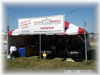
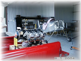
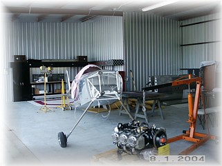
When I ordered by engine from Bart, I arranged with him to deliver it to me at AirVenture. That way, he got to display it during the show, and I saved all the shipping and import fees. Bart also threw in some extras at no charge to dress up the engine a little. This year, their tent was right outside the main doors to exposition hall A on Aeroshell Square.
It's hard to tell from the picture, but he had a nice laminated sign with my name on it. On Saturday evening during the air show, I drove my pickup right through the crowd on Aeroshell Square and we loaded the crate in the back.
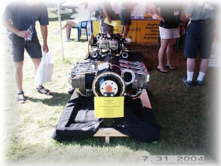
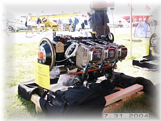
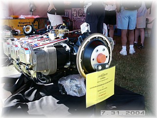
Next day, I drove home and unloaded all my goodies into the hangar. The two-ton engine hoist made it simple to lift the engine and crate bottom out of the back of my truck and on to the hangar floor. I'm now ready to start bolting things together. For the record, the engine is a Lycoming IO-540-D4A5 (260 HP) with Lightspeed Plasma II ignition w/one mag, Airflow Performance fuel injection with boost pump and filter, new Millennium cylinders, longer prop governor studs, fuel pump mod for clearing the mount, and custom painted black with chrome shroud tubes, valve covers, and intake tubes. I kind of hate to cover it up with a plenum!
Once I had everything off of the firewall, I put together my plan for my engine compartment in terms of color scheme and appearance. I decided to polish the firewall and paint everything else black, to match my engine. I ordered a stainless steel polishing kit from Caswell Plating and got after it. Polishing takes a lot of time and patience, especially since the stainless is so hard. After a couple of days and after experimenting with the instructions, I came up with the steps necessary to put a decent shine on it. It took some elbow grease but I think it will look nice when it is all done. Next steps are to mount all the accessories to the firewall before the mount and the engine get in the way. Before you cut your holes in your firewall, I'd like you to consider something. The firewall is made of stainless steel for a reason. It's to keep the flames out of the cockpit should an engine fire occur. Remember that when you cut a hole in your firewall. Will what you are putting into that hole stand up to a engine fire? Why anyone would cut a two inch hole in their firewall and then place an ALUMINUM heat box in it, is way beyond my understanding. Take a torch to a piece of aluminum and you'll understand what I mean. Enough said.
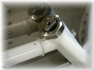
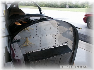
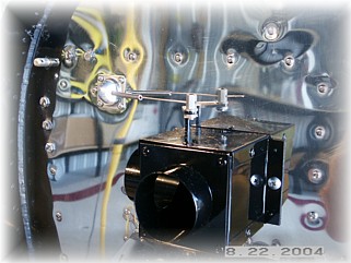
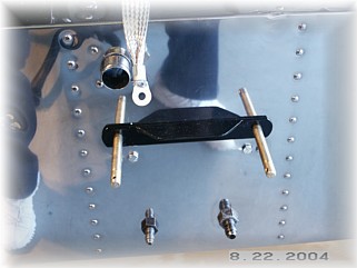
Here's the upper right hand side of my firewall. This is a stainless steel heat box with a stainless steel eyeball fitting for the cable. The other picture is the lower center of the foot box. The bottom fittings are steel fittings for the fuel and purge return lines. The upper fitting is a one inch stainless bulkhead pass through for all my power wires, like the alternator, starter, and ignition wires. Once the wires run through it, it will be stuffed and covered with fire sleeve and then plugged with fire putty.
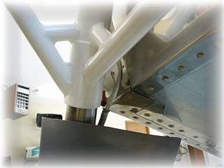
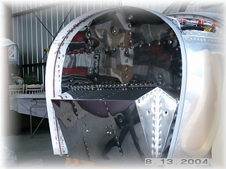
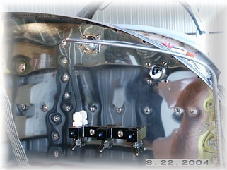
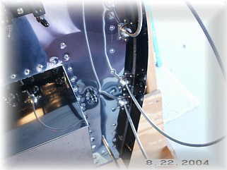
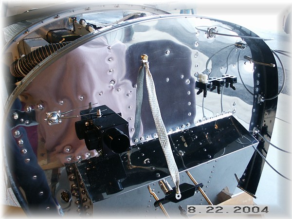
Here's the upper left hand side of the firewall. The upper eyeball fitting is the cable to the fuel purge valve. The upper 3/4 inch stainless bulkhead pass through is for all the other wires in the engine compartment that I want to separate from the power wires, like the EGT, CHT, sensor, and EI wires. This is where I chose to mount my transducer manifold. The steel fittings in the bottom will mount the 1/4 inch feeder lines for manifold pressure, oil pressure, and fuel pressure. The transducers will screw into the face of the manifold. The Nylo-Seal fitting is for the manifold pressure line that goes to the EI control module inside the cockpit. I will run that line in with the electrical wires. The other picture shows the eyeball fittings for the control cables. Also note that the brake fittings have been replaced with steel counterparts.
Here's an overall picture of my firewall. There's not much mounted there, and that's by design. I like to keep it as clean as possible so that working on the engine, and keeping this area clean, is easier. I am now ready to mount the engine. That work begins on the next page. |
||
|
"If you are out to describe the truth, leave elegance to the tailor." |