|
|
| Home-->F1 Rocket Project-->Fuselage Page 5 |
|
SITE CONTENTS
Please send your comments and suggestions to: Copyright
© 2008 by
|
Links
on this page: Passenger Seat Back Control Tubes |
|
|
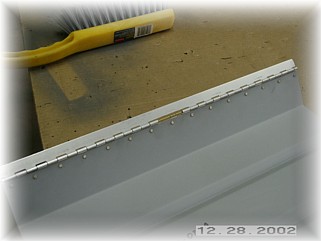
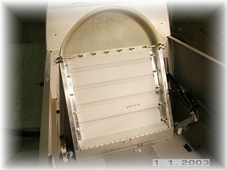
Next step is to install the rear seat back. This is one area where the instructions are pretty slim since the new flap system uses a doghouse on which the seat is installed. First thing I did was to install the hinge to the bottom of the seat back. I cut out three eyes in the middle so that I could split the hinge. I also put the flush side of the rivets on the bottom.
Then I installed the other half of the hinge on the front edge of the dog house. I bent the hinge pins down and built a couple of clips to hold the hinges down. The clips are nothing more than one eye of the hinge held down with screw and a nut plate.
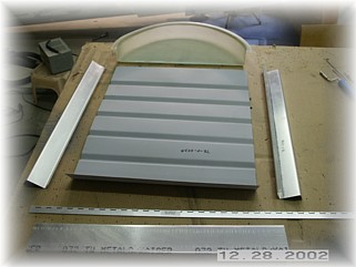
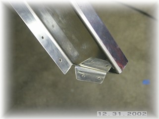
Next step was to install the side rails. I modified the bottom ends to look like this. I wanted the bottom of the rail even with the eye of the hinge and I bent a little tab on the bottom to go underneath the seat back bottom. I pre-drilled the rail and then just drilled one bottom hole to the seat back. That way, the tops of the side rails could still move around.
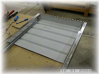
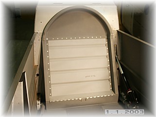
Then I placed the fiberglass top on and moved the rails around until the whole assembly was centered on the seat back. I then drilled the side rails to the seat back. Note that I left the side rails long. That is so I can leave attachment tabs on the side rail to go behind the fiberglass top piece to help secure it. I then drilled the fiberglass top to the seat back. Using the angle of the fiberglass top as a guide, I extended the lines down the side onto the side rails. I then disassembled the whole thing and trimmed up the side rails.
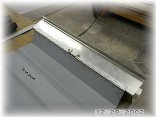
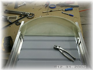
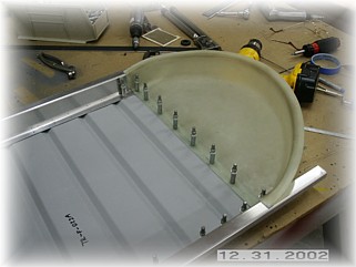
After a trial fit to ensure that it all fit in the opening, I went ahead and drilled the rest of the attach holes. You'll notice in the right hand picture that the flange on the fiberglass top does not extend all the way to the edge of the side rail. In order to provide a smooth transition, I rounded some of the remaining side rail aluminum and faired it into the fiberglass top. Later, when its all assembled, I will apply a small amount of body filler here and smooth it out. When it's done, it should look just fine.
After cleaning up the holes, I riveted everything together. The seat back fits fine is centered in the baggage compartment opening.
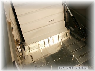
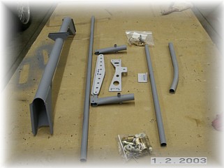
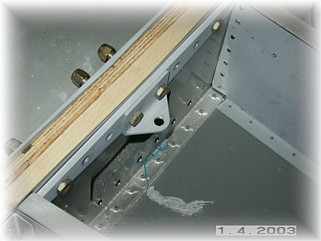
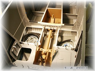
For me, I decided to install the control tubes next because I want to install both the electric aileron trim and the roll servo for my autopilot. Both of these go under the floor and need the control system in place. First step was to find suitable spacers for the spar so that I can install the reinforcing plates. I scrounged up some scrap wood from my shop and came up with the correct thickness.
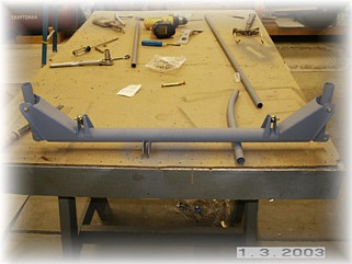
Using some spar close tolerance bolts that I had left over from my RV-6, I bolted up the spar plates and the angle that holds the front support for the control system. Over on the bench, I put everything together and trial fit it into the fuselage. This is where I noticed a problem. The attachments for the aileron torque tubes do not line up with the openings in the seat ribs. The attachments are too far aft. Advice provided by fellow builders confirmed that there will be adequate clearance with only minor trimming of the openings required.
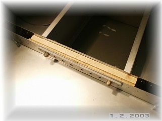
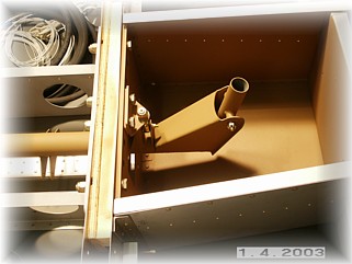
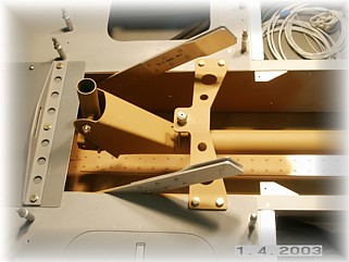
I went ahead and painted up the torque tubes and the fuselage spaces where the control system will be visible. I installed a spacer plate where the pilot crotch strap is supposed to go. That helped to move the entire system forward a little bit. I don't plan to install the crotch strap fitting as indicated in the plans. Instead, I will install some angle on the aft end of the spar reinforcing bars. That way, the crotch strap fitting will be lower than the spar and I won't have to worry about catching the family jewels on it should I have an accident. Thank you Tom Martin for the suggestion. As a result, I ordered two close tolerance bolts that are a 1/4" longer to accommodate this.
Although not shown, I installed the middle torque tube that runs from the rear control column to the bell crank back by the battery/ELT. That turned out to be a real son of a gun to install. My fat hands would not fit down inside to fit on the bolt and the washers. I ended up removing the bell crank, installing the torque tub, and reinstalling the bell crank. Have I mentioned before how I hate crawling in the rear of the fuselage? Now I'm all set to install the electric aileron trim system (RV-8 electric trim from Van's Aircraft) and my TruTrak roll servo. They both need to attach to the center control tube underneath the pilot seat floor panel. Looks crowded but they should fit. That work begins on the next page. |
||
|
"Americans used to
roar like lions for liberty; now they bleat like lambs for security." |