|
|
| Home-->F1 Rocket Project-->Horizontal Stabilizer Page 1 |
|
SITE CONTENTS
Please send your comments and suggestions to: Copyright
© 2008 by |
Links
on this page: Assemble Rear Spar Assemble Front Spar |
|
|
Assemble Rear Spar
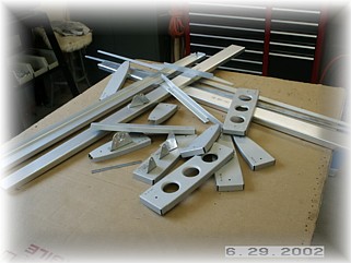
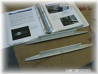
The first step in building the horizontal stabilizer is to gather all the parts together. I'll assemble the rear spar first, then the front spar. Then I'll assemble the skeleton in the jig and drill the skins. Finally the skin will be riveted to the skeleton.
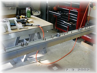
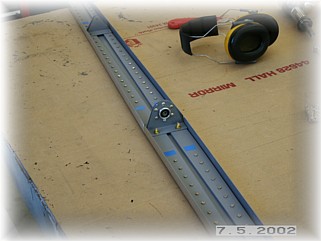
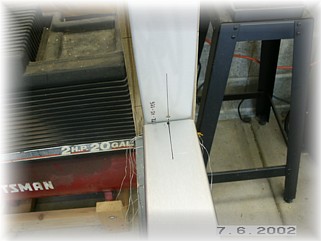
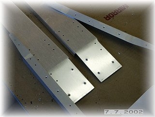
After drilling pilot holes in the two reinforcing plates, the two rear spar pieces are jigged together. The key here is to ensure that the two spar pieces are in a straight line with one another. I ran a string on top of the spar and used it to center each piece. A couple of clamps and wood scraps help to hold the spars in place until the holes are drilled. Next, lay out the hinge pieces. I use a piece of dental floss to ensure that the hinge holes are centered in the spar and in a straight line with one another. These are then drilled to the spar and to the reinforcing plates. Be careful to mark each part of the assembly so that it can be disassembled and put back together the same way it came apart. This is especially true of the hinges, which look identical but may contain slight differences which could throw off all your careful measurements. Disassemble, debur, and prime all the parts.
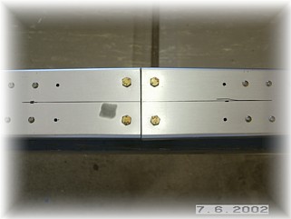
Reassemble the spar and rivet all the parts together. Be sure to mark the holes that are used to attach the ribs and leave these open. Nothing ruins your day like trying to drill out a -4 rivet that's been put in the wrong hole. You can also bolt up the center hinge. Whenever I install nuts and bolts, I add a touch of torque seal to it so that I know that it has been tightened properly. Once the project gets going, it is easy to lose track of all the various nuts and bolts on all the assemblies. The torque seal provides a visual affirmation that it has been tightened.
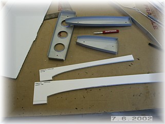
The rear spar is now ready for the jig. I first made a couple of template fixtures of the end and center ribs. These will be used to help level the skeleton in the jig. It is easier to fabricate these now before the ribs are attached to the skeleton. Using the techniques outlined in the plans, I attached hinge brackets to the jig. It's important that these are in a straight line and level with one another otherwise the rear spar will have a bow in it which will cause the elevators to bind as they move up and down. I also permanently attach the end ribs at this time. I do so now because there's no reason not to, and because it helps to stabilize the assembly in the jig.
Using my rib template, I level the end ribs and attach them to the jig upright posts with threaded rod per the plans. With everything tightened down, the spar is level and both end ribs are square to and perpendicular to the spar and in the same vertical plane with one another. Time to build the front spar.
I pre-drilled the front spar reinforcing angles per the plans. Note that the top and rear angles are drilled differently. I drilled them to #40 and then debur the holes. These are set aside for now. The front spar is assembled on top of the rear spar as it sits in the jig. However, the alignment instructions in the plans are a little vague. Note that this is the most important alignment step on the entire horizontal stabilizer so it's important to get it right. The key is to get the front spar straight from one end to the other. This is a little tricky since the spar is bent down from the attach angles to the tip. If this part is not built correctly, the horizontal stabilizer will have some twist to it and each side of the stabilizer will likely have a different incidence angle to the fuselage. Not good. I had to build two horizontal stabilizers on my RV-6 because of this so I know about this problem intimately.
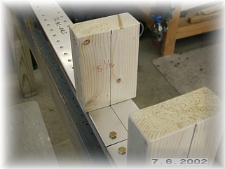
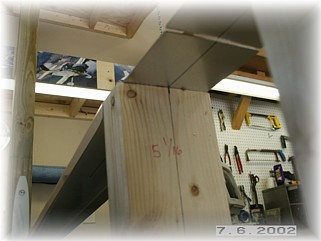
Here's how I did it. I marked the vertical centerlines on the end ribs as shown above. I also marked the centerline of the rear spar on top. These lines will be used to align the front spar once it is sitting on top of this assembly.
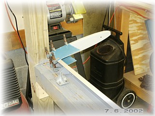
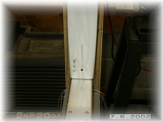
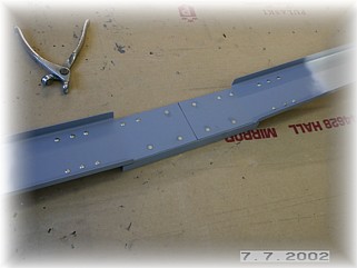
The plans call for a spacer of 5 1/16 inches in the center. I made two of these out of 2X4s. I attached the spacers to the spar using drywall screw through the open rivet holes reserved for the inside ribs. I then used a level to draw a vertical line on the spacers. These will be used to align the top spar on the centerline of the rear spar.
The top spar is now laid on top of the rear spar and on top of the spacers. I align the centerlines of the front spar with the centerlines drawn on the tip rib and on the spacers. On the tip, I used some duct tape to hold the top spar in alignment with the marks although the tape is not shown in the picture. Do this to both front spars.
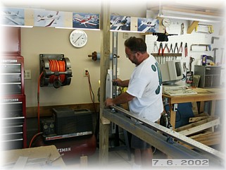
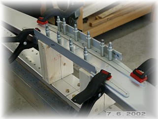
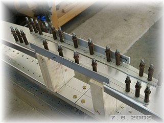
Now clamp the reinforcing angles in place. Pay particular attention to the spacing between the angles. This is an important measurement and must be exact. Once all the measurements look good and the top spars are aligned with the marks from the rear spar, I drilled the angles to the spars and to the spacers with a #40 drill. Again, this whole assembly is a little "loosey goosey" so double check the alignment as you drill each hole. Once they are all drilled and clecoed, I drilled them out to #30 one at a time.
With that, the front spar can be removed from the jig, disassembled, deburred, primed, and riveted together. Six of the rivets are dimple countersunk so that the attach plate for the vertical stabilizer can mount here. Again, the top and bottom are slightly different so check the plans carefully. With both
spars completed, the skeleton can be riveted together and re-assembled in
the jig. |
||
|
|
||
|
"Whatever
does not destroy me makes me stronger." |