|
|
| Home-->F1 Rocket Project-->Horizontal Stabilizer Page 2 |
|
SITE CONTENTS
Please send your comments and suggestions to: Copyright
© 2008 by |
Links
on this page: Assemble Skeleton Drill Skins Rivet Skins Tip Fairing |
|
|
Assemble Skeleton
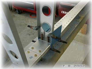
When assembling the skeleton, there are a myriad of measurements to check. It can be a little confusing where to start. I started where I knew ribs had to be positioned and ended with those ribs that could withstand a little variability. I first mounted the inside ribs over the pre-drilled holes. I drilled them to the rear spar first and then to the front spar after verifying the distance between them matched the plans. Second, I mounted the internal ribs in their pre-drilled location and squared them to the rear spar. (no picture) Third, I drilled the front spar to the end rib wherever it happened to line up. Fortunately, it lined up matching the measurement in the plans. Finally, I back-drilled the leading edge ribs over their corresponding main ribs.
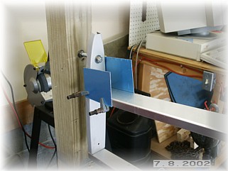
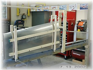
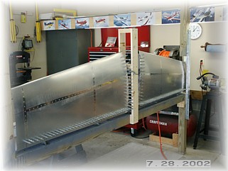
With the skeleton drilled together, it can be removed from the jig and riveted together. After cleaning the holes up, I riveted all the ribs together EXCEPT the two inner-most ribs. I left these clecoed to the spars so that they could be removed for skin riveting. If you permanently rivet these ribs now, you will have to put pop rivets in the center leading edge rib because you'll not have any way to get a bucking bar in there. By leaving the inside ribs unattached, you can reach your skinny arm (or the skinny arm of your assistant) in there to buck solid rivets. I mounted the skeleton back into the jig and attached the same center post that I used on the vertical stabilizer. The center post is used to further steady the skeleton prior to skinning and it also gives you a way to adjust the vertical alignment of the ribs so the assembly can be clamped into final position. It was at this point that I discovered a big OOPS. While trial fitting the skin, I found out that my jig was not wide enough. I could not place the skin on the skeleton in the proper position without the upright post getting in the way of the skin overhanging the tip rib. This is the same jig that I used to build my RV-7A empennage. Well, the F1 Rocket skins hang out over the edge of the end rib about an inch further than the RVs. So my jig was about two inches too narrow. After cursing for about 15 minutes, I came up with a viable solution short of disassembling the entire jig. However, I will be able to only skin one side of the horizontal stabilizer at a time. It is preferable to do both at the same time but I think I can get by without screwing things up too badly. I wouldn't recommend building yours this way, but this is my 5th horizontal stabilizer so I know enough to be dangerous.
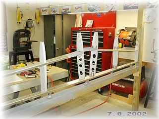
After two hours of wasted time re-jigging the skeleton, I mounted the skins and held them in place using my 1X2 homemade clamps. I used a board across the top of the jig as a "story board" and marked the position of the centerlines in the ribs so that I could duplicate the lines with the skins in place. I then marked the lines on both sides of the skin and double checked the position of the skin on the skeleton.
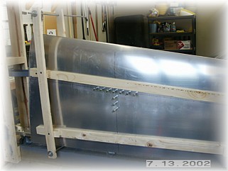
The skin is drilled to the skeleton starting in the center and working downward and outward. Again, I put a cleco in every hole to try and get the skin as tight as I can. I drilled around the 1X2 clamps where I had to until I had as many holes drilled as I could. I then removed the clamps the drilled the remaining holes. It is important when drilling the holes along the rear spar to remember two things. One, cheat a little toward the rear edge of the spar. If you drill the holes in the exact center of the web, you will have difficulty bucking the rivets because the reinforcing plate rivets on the aft face of the rear spar will get in the way. Second, determine your rivet pattern by starting in and around the hinge parts. You don't want to put a rivet in a location that you can't buck because the hinge is in the way. You can put a rivet on either side of the hinges and the spacing will work out okay.
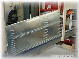
Once all the skins are drilled, I removed them and dimpled the skeleton and the skins. Care must be taken to dimple the holes closest to the leading edge as the skin wants to bow. If you don't hold it very flat, your dimple die will put a crease in the skin that will be very noticeable when you're done.
I placed the skins back on the skeleton after removing the nuts that were holding the end ribs to the jig. After double checking that both surfaces are level in the vertical plane, I began riveting the skins in the same manner as the other empennage parts. I started at the intersection of the middle rib and the forward spar, and worked my way downward and outward from there. I didn't worry about the trailing edge at this point, and I did not rivet the skin to the inside ribs. I want to be able to remove these ribs once I get the stabilizer over on the work bench. I followed this procedure on both sides of the horizontal stabilizer and on the top and bottom surfaces. At this point, the stab is sturdy enough to remove from the jig and place it on the bench.
On the bench, I removed the inside ribs so that I could reach the leading edge rivets in the middle rib. I had to borrow my wife's arm since mine is too fat. After setting those rivets, I used the squeezer to set the remaining rivets along the trailing edge and the tip rib. I didn't bother to trim the skins at this point. I will wait until I mount the stabilizer to the fuselage and attach the elevators before trimming.
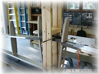
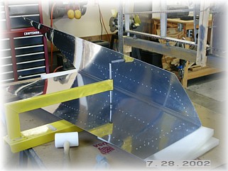
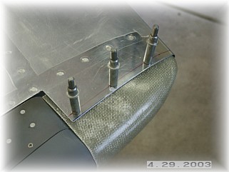
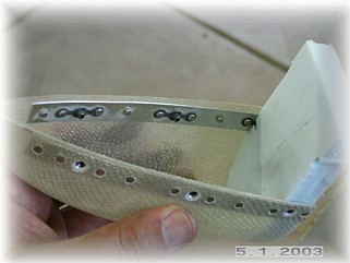
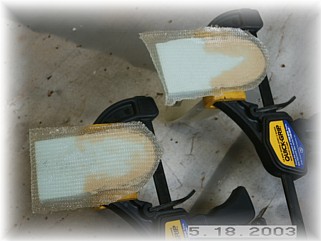
With the elevators and the elevator tips in place, I aligned the tip fairing and drilled three mounting holes. I plan to make the tip removable with some #4 countersunk screws. After trimming up the edges, I took the tip over to my bench to mount the aluminum strip and the nut plates. I also fashioned a foam rib in the end to help it hold its shape.
After a trial fit, I glassed the end ribs with two layers of cloth. I used a little microballon mixture around the edge so that I would get a good fit.
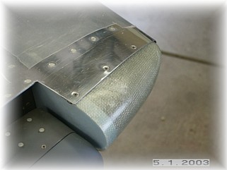
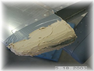
After trimming off the excess glass, I reinstalled the tip and protected the aluminum with some duct tape. I then covered the tip with a dry mixture of microballons in order to get a flush fit with the skin. Once that dried, I sanded the tip smooth and removed it so that I could fill all the pin holes with spot putty.
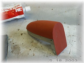
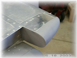
After about two or three coats of spot putty and paint, the tips are finished. This finishes up the horizontal stabilizer. It is now ready for final paint. |
||
|
|
||
|
""Goodness
is the only investment that never fails." |