Upper/Lower Control Arms
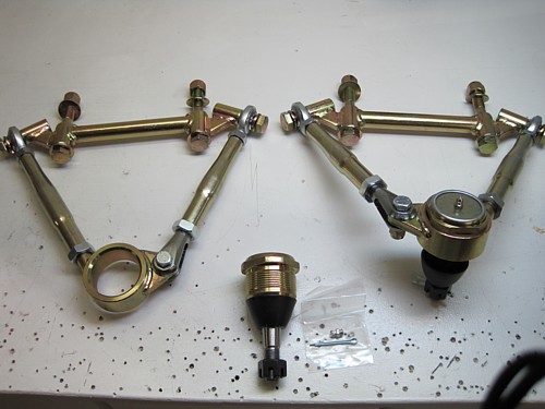
Here is a shot of the
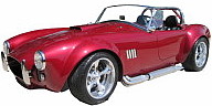
upper control arms assembled. It took me awhile to find all the parts since
they are in various boxes. Here are the pertinent notes:
Long arms go onto the threaded tab of the ball
joint cup.
Tabs on the ball joint cups point towards the
rear to clear the shock tower
Clevis goes on the end of the short arm and
connects to the tab
Be sure to use some Blue Locktite (if you are
doing final assembly) on the ball joints and the bolts that hold the long
arms to the mounting brackets
It is important to
note that the HEIM fittings are tightened down so that they are not clocked
to one side or the other. They should be straight up and down when
tight. If they are not, they will wear prematurely. Mine are loosey goosey for now since I'm not in final assembly.
Also I noted that some
builders have felt that the ball joints provided fit a little too loosely in
the fittings. I agree with them. The fix to this is to order
some replacement Moog parts and I plan to add those to my next part order.
I will swap these out once I get them. For now, they will do just fine
for rolling around the garage.
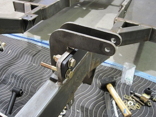
Before mounting the
upper control arms to the frame, I mounted the mounting plate to each side.
I used the longer bolts in the lower holes to align the part while just snugging down the shorter bolts. Once I was sure of the fit, I
tightened everything down and pulled the longer bolts.

Here they the upper
control arms
installed on the left front of the frame on the mounting plate. The mounting bolts are left
long so that spacers can be installed if necessary to adjust the outward
alignment of the upper control arm.
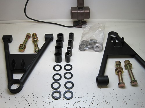
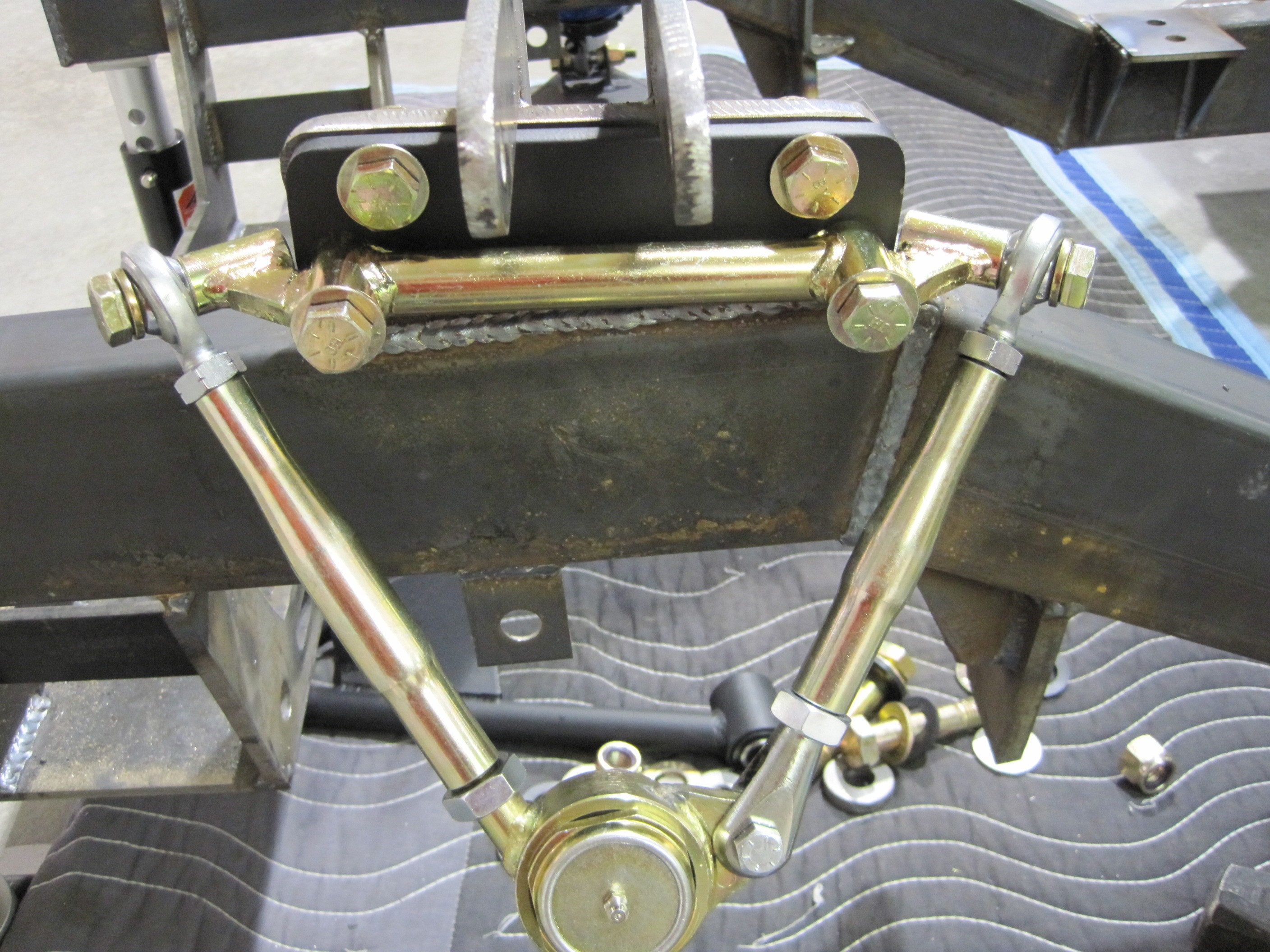
Here are all the parts for
the lower arms. The Delrin bag contains the inserts and the steel
sleeves that slip into the pivot points of the arms.

There is a bag of
spacers that you use to adjust the position of the arm forward and back.
Note that the longer bolts are used on the forward pivot point. This
is a picture of the left front looking at it from inside the engine bay.
To start with, I installed just a thin spacer on the short (rear) bolt.
According to Brian, you want the arm as far rear as you can so the front
wheel will clear the wheel well properly.
You will have more spacers than you need. I just stuck them on the end
of the bolts, in front of the nut for now. I'm not sure if they
are used later for something else or not. The steel sleeve is slightly
longer than the Delrin bushing. That is to provide a shoulder for the
Delrin washers to slide up on. Make sure you have these parts in
alignment before tightening down the fastener.
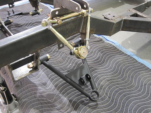
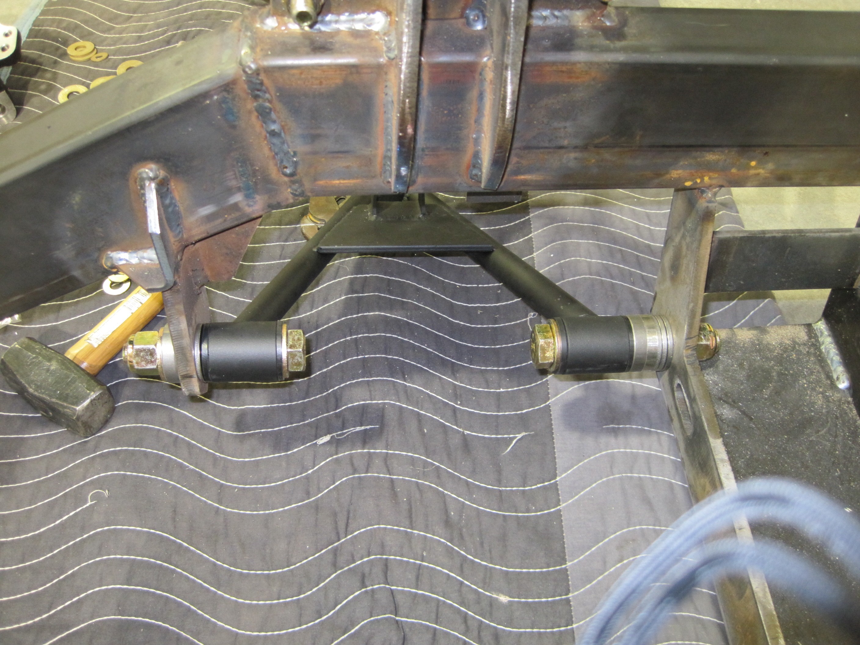
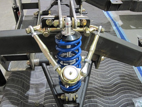
Here's another shot of
the left front. Note the tab on the upper control arm towards the rear
and the extra spacers mounted under the nut on the front bolt of the lower
control arm. Note that in this picture, the mounting plate for the
upper control arm is not installed on this picture. Ignore that.
This picture just helps to show the orientation of the arms.
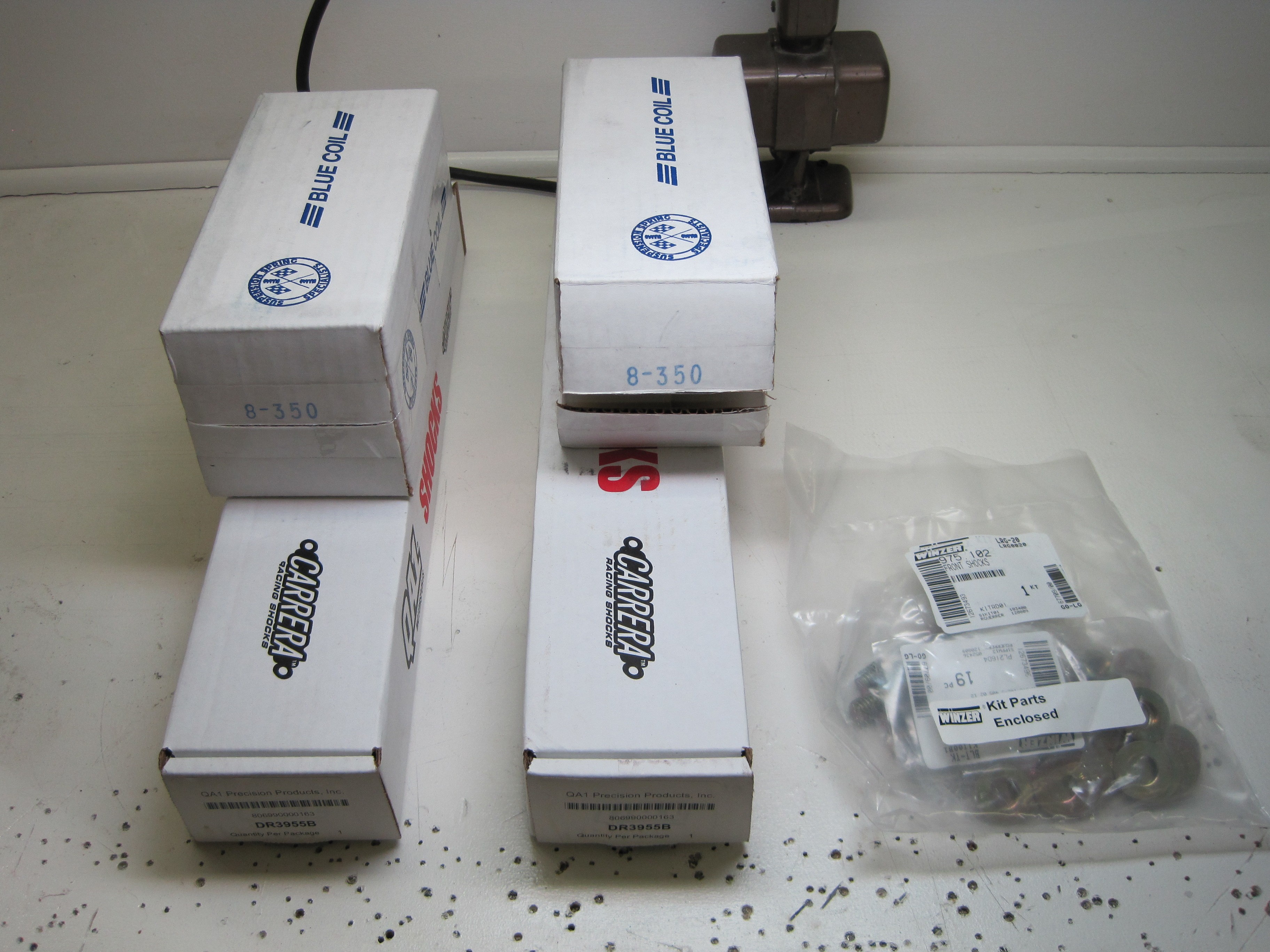
Shocks
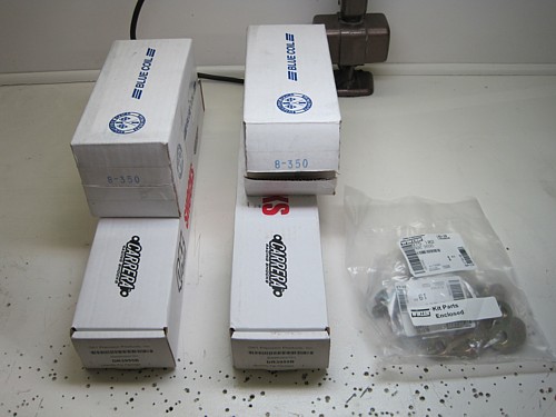
Dig out the bag of fasteners
for the front shocks from the box along with the 350 springs and shocks.
Note that there are two sets of springs. The 350's go on the front and
the 275's go on the rear.
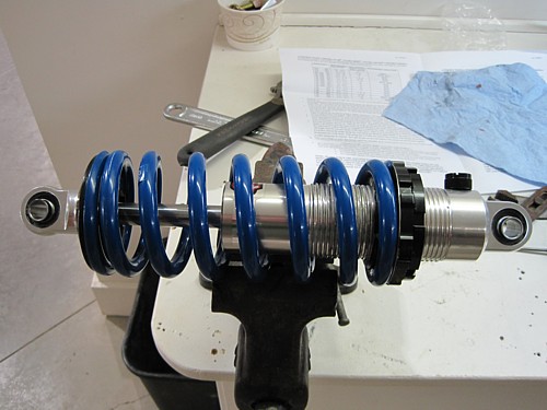
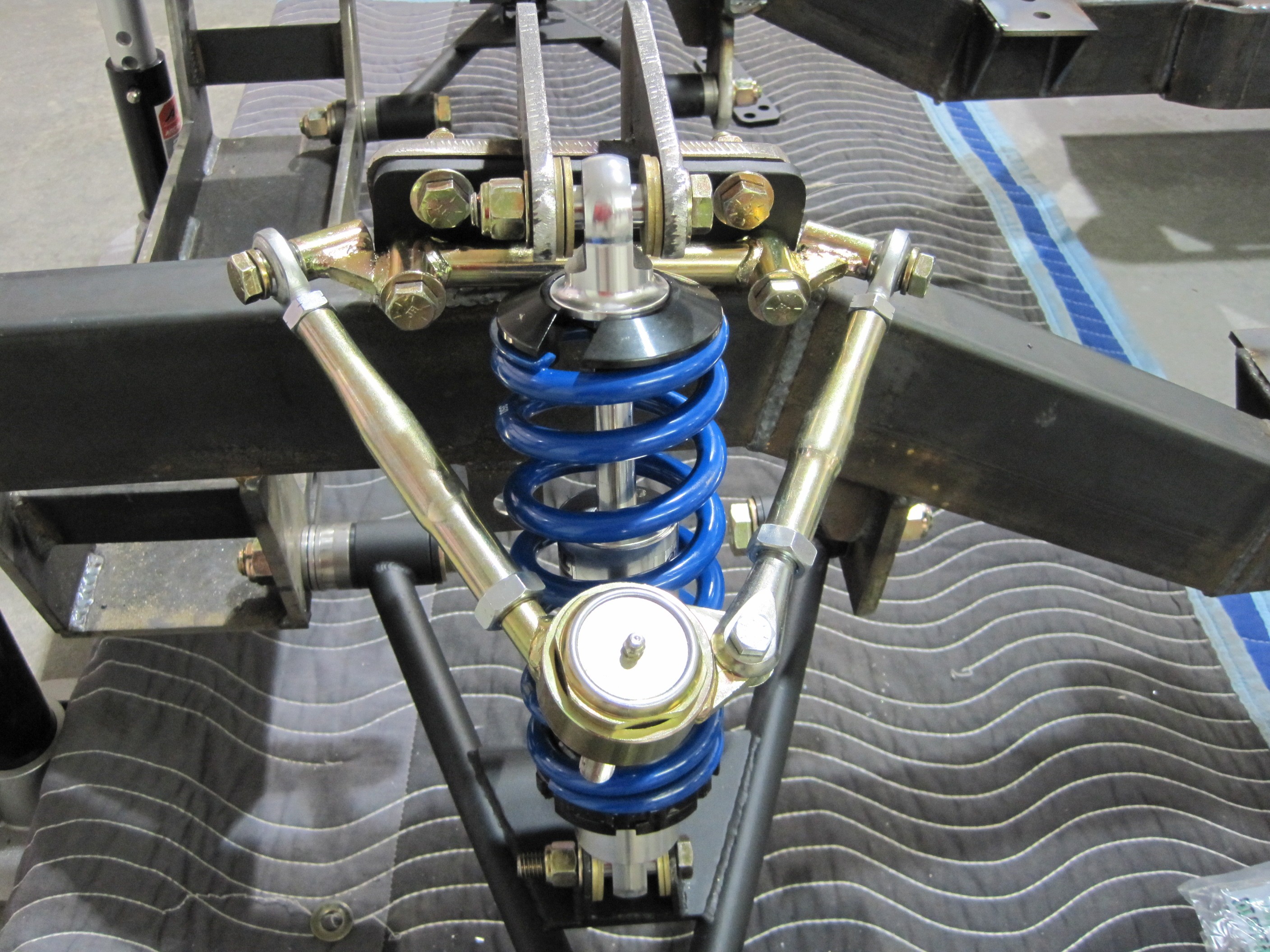
I followed the instructions
that came with the shocks. You will need some anti-seize on the
threads of the shock body and bottom washer per the instructions. I
set the shocks to their softest setting and compressed the spring hand
tight. Be careful inserting the clip rings that hold the inserts into
the mounting holes. It is easy to think they are in without them fully
snapping into the groove. I had to tap mine with a screwdriver blade
to make sure they clicked into the groove.
Install it on the frame
using the fasteners provided. Make sure you orient the shock correctly
top and bottom (ask me how I know). Also mount it so that the
adjusting knob in towards the inside so you will be able to reach it from
under the car. The instructions say to use washers as spacers for
mounting the shocks. Well, I didn't have enough of them so I went to
the hardware store and bought some hardened ones to use here.
|